Working Style
The Working Style page enables you to define pre-processor settings and parameters used for operation default values and for software only.
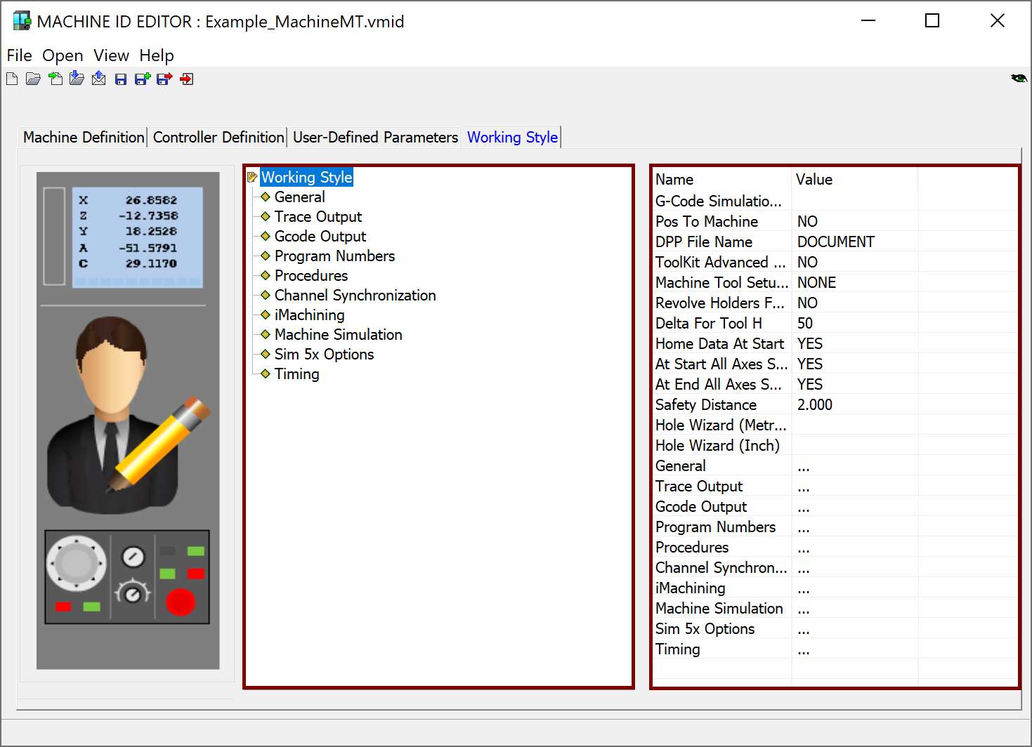
The left pane contains the Working Style tree. Clicking the Working Style header displays in the right pane the available settings. Some are global settings and some are a duplication of those listed under the Working Style header.
Like the Controller settings, some parameters are inherited from the *.prp file used in earlier versions of SolidCAM.
Working Style Settings
The following global settings are not related to a specific Submachine or Channel.
Parameter Name |
Description |
PRP Name |
| Pos To Machine | This parameter enables writing posts in the new style. SolidCAM provides GCode output for a number of coordinate systems. | pos_to_machine |
| DPP File Name | Name of the *.dpp file used to customize the Documentation output. | doc_processor_name |
| ToolKit Advanced View mode | This parameter enables or disables the ToolKit Advanced View mode. | -- |
| Machine’s Tool Table Name | Defines the tool table name of the machine to be the Part Tool Table. | tool_table_name |
| Delta For Tool H | The delta address of the Offset Table in the machine controller. Delta will be added to the tool offset in Part Tool Table. | Delta_for_TOOL_H |
| Home Data At Start | Defines the location where the @home_data will be printed: either at the beginning of the program after @def_tool or at the end of the program after @end_of_program. | home_data_at_start |
| At Start All Axes Set To Home Ref | Determines if all axes are shown in Home Reference position for START PROGRAM item in the Move List Pane of Machine Simulation, when simulating the entire part. | -- |
| At End All Axes Set to Home Ref | Determines if all axes are shown in Home Reference position for END PROGRAM item in the Move List Pane of Machine Simulation, when simulating the entire part. | -- |
| Safety Distance | Defines the default value for the Safety distance parameter used in various operations. | safety_dist |
| Hole Wizard (metric) | Defines which Hole Wizard Machining Process is used by default with the current machine (metric template). | -- |
| Hole Wizard (Inch) | Defines which Hole Wizard Machining Process is used by default with the current machine (inch template) | -- |
For the remaining Working Style settings, you can click its name in the left pane to display the corresponding parameters separately in the right pane.
When the Machine Definition includes more than one Submachine and/or Channel, you only have to define the settings for the first Submachine/Channel (ID No. 1). All others assume the parameters of the first Submachine/Channel.
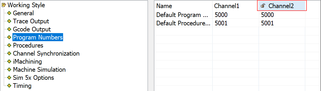
For some settings (General, Gcode Output and Program Numbers), the parameters are locked and the Submachines/Channels are shown with a lock icon.
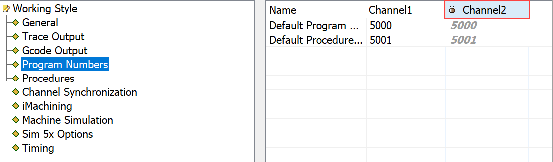
If the settings need to be defined differently for each Submachine/Channel, you can click the lock icon to enable editing of the parameters.
This page includes the following sections: