Levels page
This page enables you to define the machining levels for the operation.
Clearance plane
The Clearance area is the area where the tool movements can be performed safely without contacting the material. The tool movements in the Clearance area are performed with the rapid feed.
This section enables you to define the Clearance area by plane. The tool performs a retract movement to the Clearance area plane, and then a rapid movement in this plane.
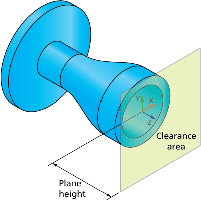
The plane orientation is defined by a vector normal to the plane. With the In X and In Z options, SolidCAM enables you to define this vector as one of the Coordinate System axes (X or Z).
When the In Z option is chosen, the Plane height parameter defines the distance between the appropriate Coordinate System plane and the Clearance area plane.
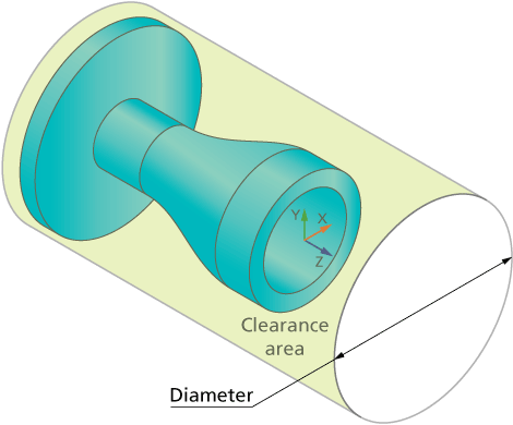
When the In X option is chosen, the Plane height parameter is changed to Diameter and defines the diameter of the Clearance area plane.
Levels
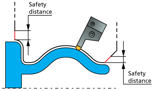
The Levels parameters enable you to define the Retract and Safety distance to approach and retract from the part.
In the Clearance area, the tool turns to the final orientation for the first cut. After the rotation, the tool performs a rapid descent movement to the level specified by the Retract distance parameter.
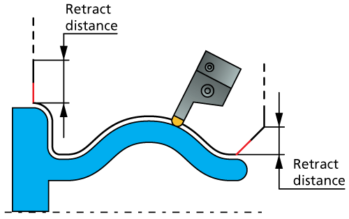
After the descent movement to the Retract distance level, the tool starts the approach movement to the material. The approach movement consists of two segments. The first segment is performed with rapid feed up to the Safety distance. From the Safety distance level, the approach movement is performed with the cutting feed.
Rapid retract
This option enables you to perform the retract movement with rapid feed.
When this check box is not selected, the tool moves to the Safety distance with the feed defined for the Retract Feed parameter.
When this check box is selected, the retract movement is performed with rapid feed.
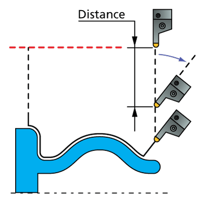
Keep initial orientation until distance
This section enables you to alter the tool tilting for rapid movements in the Clearance area. When the tool descends from the Clearance area till the first cutting pass, it can be from the very beginning tilted according to the tool axis control parameters definition, or it can descend straight until a specified distance and then get tilted as required.
When the check box is not selected, the tool descends from the Clearance area, tilted according to the tool axis control parameters definition. After it has performed the cutting passes and the lead out movement, the tool returns to the Clearance area, tilted in the same manner.
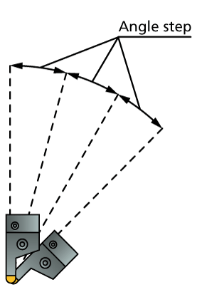
When the check box is selected, the tool descends not tilted, parallel to the vector normal to the plane, until it reaches the given distance to the beginning of the link movement, and then gets tilted as required. After it has performed the cutting passes and the lead out movement, the tool ascends up to the specified distance, gets adjusted to its initial angle, and returns to the Clearance area parallel to the vector normal to the plane. The Distance parameter defines the distance to/from the beginning of the link movement, at which the tool orientation changes.
The Angle step for rapid moves parameter defines the angle increments for the tool tilting.