Data
This tab enables you to define the feed, spin and tool offset parameters for the tool chosen in the operation.
Feed
Feed units
This section defines the type of feed units.
Feed normal – specifies the normal working feed value.
Feed finish – specifies the finishing feed value.
Retract feed – specifies the feed of the tool movements from the material to the retract level.

This Retract feed parameter is available only for Simultaneous Turning operations.
In the Metric system, the feed units can be expressed in:
mm/min - millimeters per minute;
mm/rev - millimeters per revolution.
In the Inch system, the feed units can be expressed in:
inch/min - inches per minute;
inch/rev - inches per revolution.
Spin
Spin units
This section defines the type of spin units.
Spin normal – specifies the spin value for normal turning.
Spin finish – specifies the spin value for finish turning.
For each Spin parameter, you can choose the type of spin units individually, which can be expressed in revolutions per minute – S (rpm) or meters per minute– V (m/min).
Gears
When meters per minute (V) is chosen for either of the Spin parameters, the Reference diameter of rotation is calculated automatically.
The Min. Spin and Max. Spin values enable you to manually define the spin limits in rpm, which can be used to maintain a constant surface speed. Alternatively, the spin range can be taken automatically from the defined Gear settings in the VMID by choosing the Stay in gear limits option.
If the drive unit used in the operation has more than one Gear, you can enable the automatic switching of those Gears according to their spin range by clicking the Auto Gear-switching check box.
The Gear parameters are available if either of Spin rate or Spin finish is defined in V units.
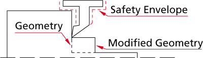
Safety parameters
The Safety angle parameter defines the angle between the material and the cutting edge of the tool; this prevents the cutting edge of the tool from colliding with the material.
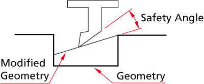
The Safety envelope parameter defines the safety distance between all the non-cutting edges of the tool and the material; this ensures that the non-cutting edges of the tool do not crash into the material.
Offsets
The Tool offset number parameter determines the position of the tool in the tool offset table of the CNC-Machine.
Second offset
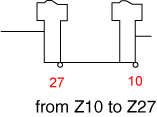
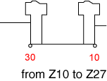
This parameter defines a tool offset number in the machine tool table. It specifies the offset number of the other side of the tool and is used for a groove cycle for a single line groove geometry. If the Second offset number is equal to the tool number, then the groove line is shortened by a length equal to the G parameter of the grooving tool; otherwise the whole line is handled by the machine cycle.
|
|
Second offset is equal to the tool number |
Second offset is not equal to tool number |
This parameter is available for Grooving operation only.
Related Topics