Closed slot
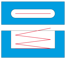
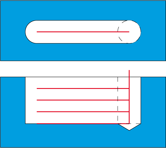
This ToolBox Cycles strategy enables you perform the machining of a closed slot with the width equal to the tool diameter. By default, the machining is performed in the zigzag manner; the last cut is horizontal to clean the slot floor.
Geometry definition
The strategy provided by this sub-operation can be performed only on closed chains; accordingly, the geometry should contain at least one closed chain. The geometry containing only closed chains is considered as suitable. The geometry containing only open chains is considered as unsuitable. The mixed geometry containing a number of open and closed chains is considered as suitable. In such geometry, all the open chains are ignored during the tool path calculation.
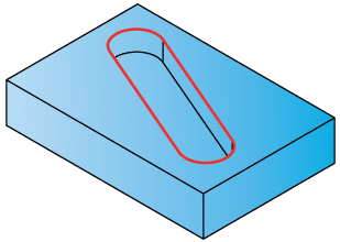
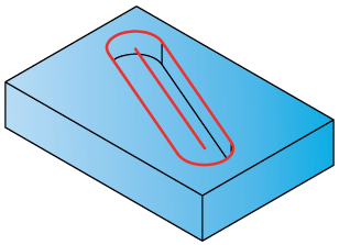
This sub-operation is intended to perform the closed slot machining. The closed slot shape should be chosen in the manner as shown below.
|
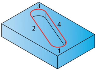
The ideal slot shape to be machined with this sub-operation consists of two arcs of the same radii (see entities 1 and 3 in the illustration below) and two parallel elements connecting the end points of arcs (see entities 2 and 4 in the illustration below).
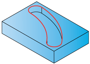
In this case, these parallel elements are lines, but the shape can be different. The major criteria of proper work of this sub-operation is the parallelism between these elements. For example, the shape shown in the illustration below can also be successfully machined by this sub-operation.
The geometry chains where the parallelism between two elements is not maintained will be machined with errors. |
When the geometry is defined, SolidCAM determines the center line of the slot. The machining is performed along this line.
Technological parameters
Step down
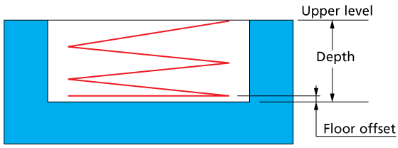
This sub-operation enables you to generate the vertical zigzag tool path starting from the Upper level to the specified Depth of the slot (modified with the specified Floor offset). When the machining depth is reached by a number of zigzag cuts, the horizontal cutting pass is generated at the machining depth, cleaning the floor of the slot.
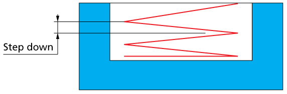
The zigzag tool path consists of a number of inclined cuts; the depth of a single inclined cut is defined with the Step down parameter.
In some cases the machining depth (the result of subtracting of the Floor offset from the Depth) cannot be divided by the Step down without the rest. In this case all the inclined cuts except for the last cut are performed with the specified Step down. The last cut is performed at the level of the rest of the depth.
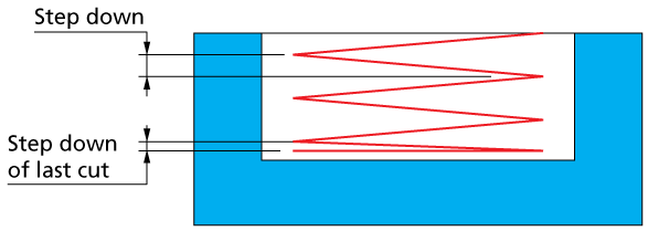
In other words, the cutting passes are not evenly distributed along the slot depth.
When the Equal step down option is activated, SolidCAM enables you to specify the Max. Step down parameter. SolidCAM automatically determines the actual Step down value as smaller nearest neighbor to the specified Max. Step down parameter; this actual Step down value should assure the equal distribution of inclined cutting passes.
Offsets
This section enables you to define Floor offset for this sub-operation. The Floor offset is applied to the floor of the slot; the specified offset is left unmachined during the current sub-operation. When the Floor offset value is specified, SolidCAM performs the machining by the Z-levels defined with the Step down parameter. The machining is performed until the Floor offset.
Pre-Drilling
This sub-operation can extract, store and use data from a previously applied Drilling operation to calculate approach points automatically.
Use Pre-Drilling Operations
Upon selecting the Use Pre-Drilling Operations check box, the definition windows are activated. When a Drill operation is chosen from the list, the associated X- and Y-coordinates appear in the Drill positions list. The drill diameter and positions data are used for the approach point calculations.
When Pre-Drilling data is defined, the machining is performed using all horizontal cuts instead of the default zigzag manner.
All rules regarding the Geometry definition are applicable. For the Technological parameters, Step down defines the depth of a single horizontal cut.
According to the Drill positions data, the tool approaches the slot and performs a vertical entry to the Step down depth. After the first horizontal cut is completed and for each successive cut, the tool returns to the approach point at the Step down depth. If the pre-drilled hole is located arbitrarily (in the middle of the slot for example), the tool machines in one direction and then machines in the other direction after returning to the approach point at the Step down depth.
|
The milling tool used to cut the slot will enter into the pre-drilled hole only if its diameter is equal to the diameter of the previous drilling tool. The drilling tool also must have reached the slot floor at the full diameter (and not the cutter tip). Otherwise, the Pre-Drilling data is ignored. |