Geometry
The Geometry page enables you to define the 3D model geometry for the SolidCAM Edge Breaking operation.
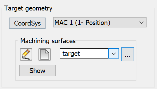
Target geometry
The Target geometry section enables you to specify the appropriate Coordinate System for the operation and to define the machining geometry.
Coordsys
SolidCAM enables you to define the Coordinate System for the operation by choosing it from combo-box or by selecting it from the graphic screen by clicking CoordSys. The CoordSys Manager dialog box is displayed. Together with this dialog box, SolidCAM displays the location and axis orientation of all Coordinate Systems defined in the CAM-Part.
To get more information about the Coordinate System, right-click the CoordSys entry in CoordSys Manager and choose the Inquire option from the menu.

The CoordSys Data dialog box is displayed.
When the CoordSys is chosen for the operation, the model is rotated to the appropriate orientation.
The CoordSys selection operation must be the first step in the geometry definition process.
Machining surfaces
After the Coordinate System is chosen, define the 3D Model geometry for the SolidCAM Edge Breaking operation. The Machining surfaces are the entire model or any surface(s) of the design model.If you have already defined 3D Model geometries for this CAM-Part, you can select a geometry from the list.
![]() enables you to define a new
3D Model geometry for the operation with the 3D
Geometry dialog box.
enables you to define a new
3D Model geometry for the operation with the 3D
Geometry dialog box.
![]() displays the Browse Geometries
dialog box that enables you to visualize the geometry during the selection
process; the selected geometry is highlighted in the SOLIDWORKS
Graphics Area.
displays the Browse Geometries
dialog box that enables you to visualize the geometry during the selection
process; the selected geometry is highlighted in the SOLIDWORKS
Graphics Area.
Show displays the chosen 3D model geometry in the SOLIDWORKS window.
|
When you choose the geometry from the list, the related Coordinate System is chosen automatically. |
Edge
Edge Definition - You have 2 options to define break edges:
Auto detect - When this option is selected, all edges are automatically extracted from the selected part surfaces. You can manually select the edges that are to be excluded from machining.
Excluded curves
Enable this check box to select the edges not required to be machined.
Click
![]() , the Geometry
Edit dialog box is displayed. From this dialog box, you can select
both the open and closed curves that you wish to exclude from machining.
, the Geometry
Edit dialog box is displayed. From this dialog box, you can select
both the open and closed curves that you wish to exclude from machining.
If you have already defined the edges for this CAM Part, you can select the edges from the drop-down list.
![]() displays the Browse Geometries
dialog box that enables you to visualize the geometry during the selection
process; the selected geometry is highlighted in the SOLIDWORKS
Graphics Area.
displays the Browse Geometries
dialog box that enables you to visualize the geometry during the selection
process; the selected geometry is highlighted in the SOLIDWORKS
Graphics Area.
Show displays the chosen edges in the SOLIDWORKS window.
|
The Edge curve option is disabled when Auto detect is selected |
Automatic edge detection
Min. detected edge angle- This field allows you to enter the angle value for the edges. All the edges with an angle greater than the specified value are classified as sharp edges. The Default value is set at 15 degrees.
Min. Detected edge length- This field allows you to specify a value to exclude tool path segments that are shorter than the specified value. By default, this option is disabled.
Limit detection area by height – When this check box is selected, it enables you to machine sharp edges in a specific area only. The area can be limited by a reference axis and a Start and End value with respect to the reference axis. Only the sharp edges between those boundaries are considered for machining.
Reference
axis – You can specify
the direction of the axis (X,Y,Z)
in which the area will be limited. When the User-defined
axis is selected, ![]() is enabled. Select
is enabled. Select ![]() to open the Direction window.
You can then specify the values (dX, dY and dZ) or select
to open the Direction window.
You can then specify the values (dX, dY and dZ) or select ![]() in the Direction window to select the required X,Y,Z
points.
in the Direction window to select the required X,Y,Z
points.
Reference Axis Base point - This option enables you to define the position of the rotation axis. When you click Select point, the Select point dialog box is displayed with the coordinates of the point you pick on the model.
Start and End - The axis base point values can also be manually entered and/or edited in the Start and End fields.
|
If the Auto detect fails for an edge, the edge cannot be machined, even if you define the edge curve manually. |
Manually - You can manually select the surface edges of the part geometry. Multiple curves can also be selected. Only the selected curves are machined.
Manually defined edges
Edge Curve
![]() enables you to define a new edge curve geometry using the Geometry Edit dialog box.
enables you to define a new edge curve geometry using the Geometry Edit dialog box.
![]() enables you to edit an existing edge curve geometry.
enables you to edit an existing edge curve geometry.
If you have already defined the edges for this CAM Part, you can select the edges from the drop-down list.
![]() Clicking this button displays
the Browse Geometries dialog
box that lists all the geometries of the type suitable for the chosen
operation.
Clicking this button displays
the Browse Geometries dialog
box that lists all the geometries of the type suitable for the chosen
operation.
Show displays the edge curves in the SOLIDWORKS window.
|
The Excluded curves and Automatic edge detection sections are disabled when Manually option is selected. |