Gouge check
The Gouge check page enables you to automatically detect and avoid the possible collisions between the tool (with the tool holder) and the workpiece.
Degouging
Check surfaces
This option enables you to choose a number
of non-drive surfaces on the model as the Check
surfaces and perform the gouge checking for them. This section enables
you either to choose the Check
surfaces geometry from the list or define a new one with the ![]() button.
button.
Clicking ![]() gives you the options to choose the Check
surfaces geometry
gives you the options to choose the Check
surfaces geometry
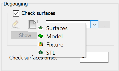
Select the Check surfaces check box to enable the Degouging section.
Clicking ![]() button displays a
list of options that can be additionally selected for collision checking.
button displays a
list of options that can be additionally selected for collision checking.
Selecting Surfaces
![]() from the list displays the Select
faces dialog box. This dialog box enables you to select one or several
check faces of the SOLIDWORKS model.
from the list displays the Select
faces dialog box. This dialog box enables you to select one or several
check faces of the SOLIDWORKS model.
Selecting Model
![]() from the list displays the 3D Geometry dialog
box. Using this dialog box, you can define the 3D Model geometry.
from the list displays the 3D Geometry dialog
box. Using this dialog box, you can define the 3D Model geometry.
Selecting Fixture
![]() from the list, displays the Model
dialog box. This dialog box enables you choose or define the fixture to
mount the machining part.
from the list, displays the Model
dialog box. This dialog box enables you choose or define the fixture to
mount the machining part.
Selecting STL
![]() from the list, displays the Choose STL dialog box. You can choose check
surfaces geometry from an STL file.
from the list, displays the Choose STL dialog box. You can choose check
surfaces geometry from an STL file.
![]() enables
you to choose the necessary STL file. The full name (including the path)
of the chosen STL file is displayed in the STL
file edit box. The Show
button enables you to display the chosen STL file in a separate window.
enables
you to choose the necessary STL file. The full name (including the path)
of the chosen STL file is displayed in the STL
file edit box. The Show
button enables you to display the chosen STL file in a separate window.
Check surfaces offset
This parameter is enabled only in case when the Check surfaces option is chosen for the gouge checking. SolidCAM uses Check surfaces offset value to define the machining allowance for check surfaces.