Machine Setup
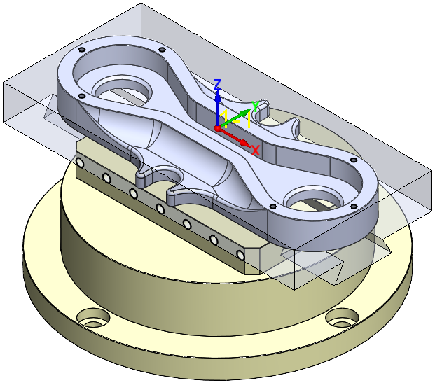
SolidCAM enables you to define the part fixtures such as clamps, vises, jig plates, etc. Using the Setup feature, you can define the Fixtures and their location relative to the Coordinate Systems associated with the table where the part is located. This unified representation of all setup data allows you to get a more realistic picture during simulation and check possible collisions between the cutting tools and fixtures. |
 |
To define a new Setup:
- Right-click the Operations header in the CAM Manager tree and from the Machine Setup submenu, choose either Add at start of operations tree or Add at end of operations tree to specify the location for adding the setup. The Machine setup dialog box is displayed.
The Customize option enables you to deselect the items you rarely use and want to hide and keep selected the items you want shown.
|
You can also right-click any existing operation and from the Machine Setup submenu, choose to add the setup Before or After the selected operation.
|
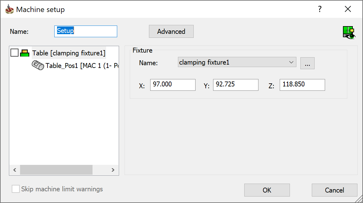
- In the Name field, type a new setup name or use the default one. This name will be displayed in the CAM tree.
![]()
The Table Tree View by default displays the Table name and Position number of the respective table (fixture) or None. Right-click on Table name and position number to edit Stock in.
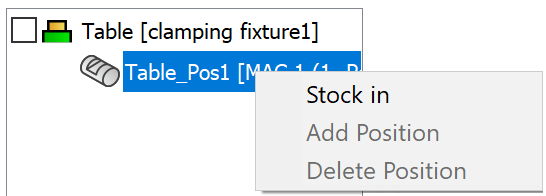
The Stock in option enables you to specify the part location on the machine table. Only one table at a time can hold the part.
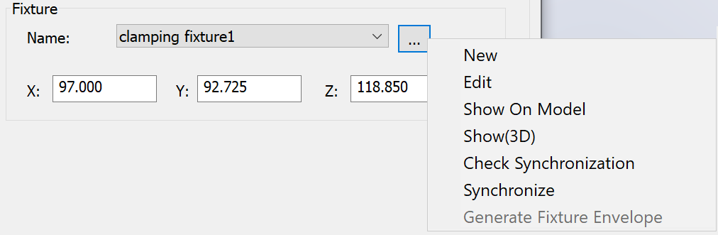
Clicking Table displays the Fixture field. The Fixture field enables you to choose or define the fixture to be used with the specified table. To define the fixture, click the drop-down list and choose ... or, click
 and select New. The Model dialog box is displayed.
|
 |
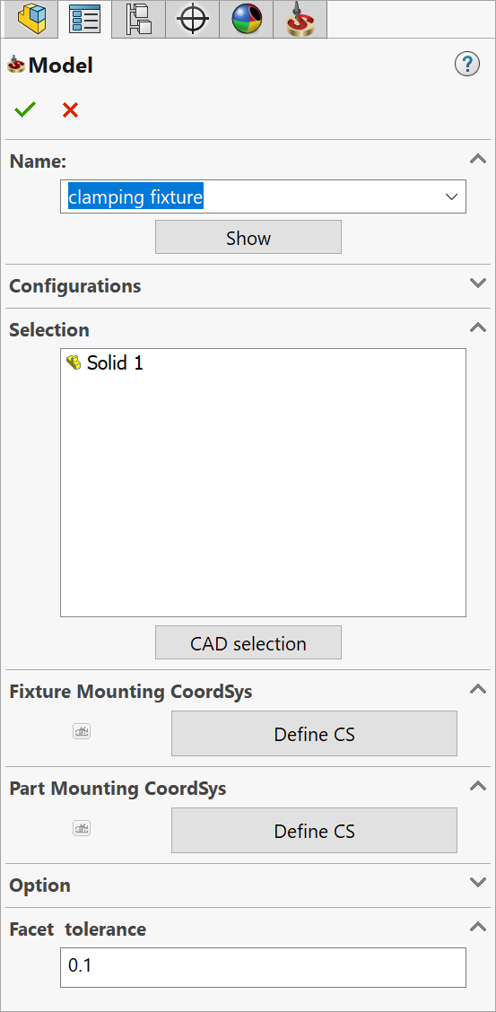
Name
This option enables you to define the name of the geometry. SolidCAM offers you the Default Geometry name that can be edited.
Configurations
This option enables you to switch between SOLIDWORKS configurations. Choose the relevant configuration for the geometry definition.
CAD selection
This option enables you to select the 3D geometry with the SOLIDWORKS tools.
|
When an object is selected in the CAD selection mode, the CAD selection button changes to Resume. |
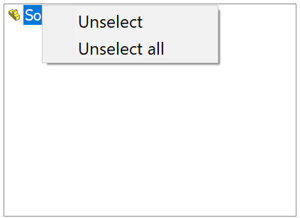
List of selected objects
You can select an object by clicking on it. When an object is selected, its icon is displayed in the list in the bottom of the dialog box.
To unselect the object, click on it again or right-click on its icon in the list and choose Unselect from the menu. To remove selection from all objects in the list, click Unselect all.
Fixture Mounting Coordsys / Part Mounting Coordsys
These options are enabled only when you select the fixture.
With these options you can define the coordinate systems for fixture and
part. The position of fixture coordsys is relative to station coordsys
and the position of part coordsys is relative to part mounting coordsys.
Clicking Define CS button displays
the Coordsys dialog box. Once the CS is defined,
![]() enables
you to visualise the defined coordinate system directly on the CAM-Part.
enables
you to visualise the defined coordinate system directly on the CAM-Part.
Facet Tolerance
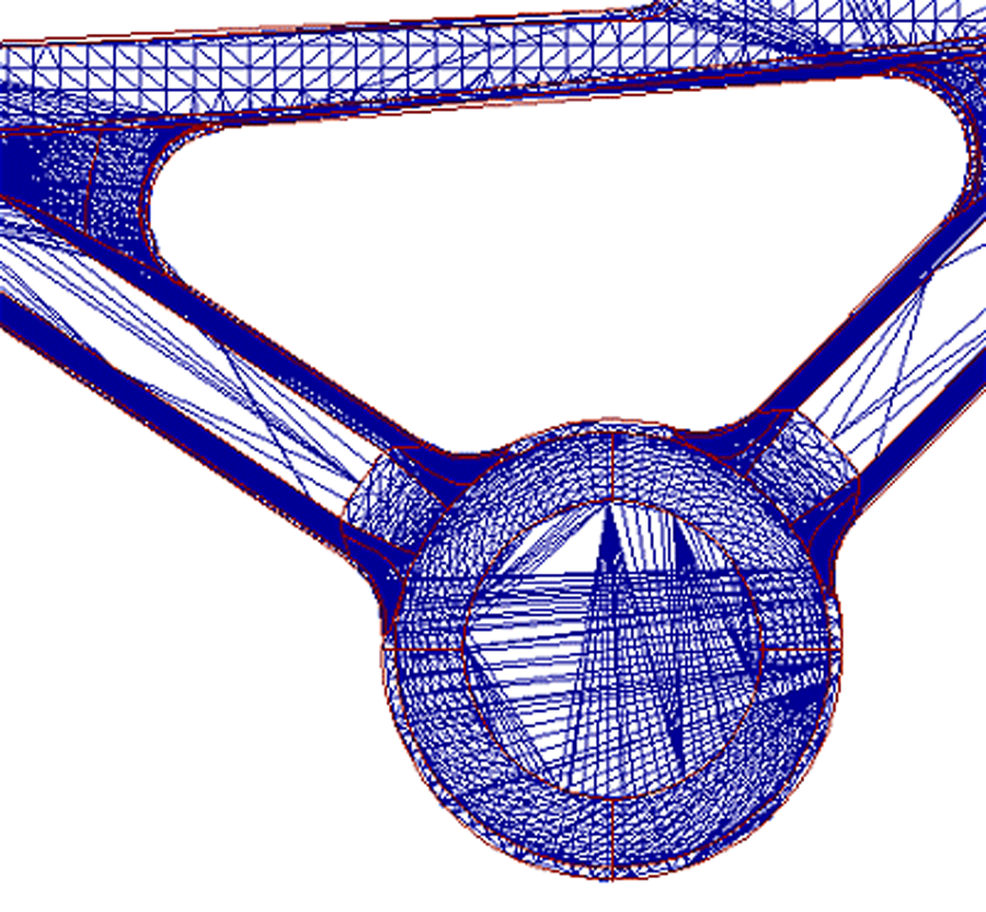
This tolerance controls the maximum deviation of the mathematical representation from the original solids and surfaces of your model.
The 3D Model geometry is triangulated and the resulting facets are saved in the <model_name>.fct file in the CAM-Part's folder. The triangulation is performed on the 3D Model geometry when you use it for the first time. If you use the 3D geometry in another operation, SolidCAM checks the tolerance of the existing *.fct file of this geometry. It does not perform another triangulation as long as the *.fct file is created with the same surface tolerance. |
 |
5. Click ![]() to confirm your selection.
The Machine setup window opens.
to confirm your selection.
The Machine setup window opens.
6. Define the linear values for X,Y, Z axis for fixture.
|
For Mill-Turn parts, the Model dialog box includes also the options of Standard Chuck and User-Defined Chuck.
|
7.
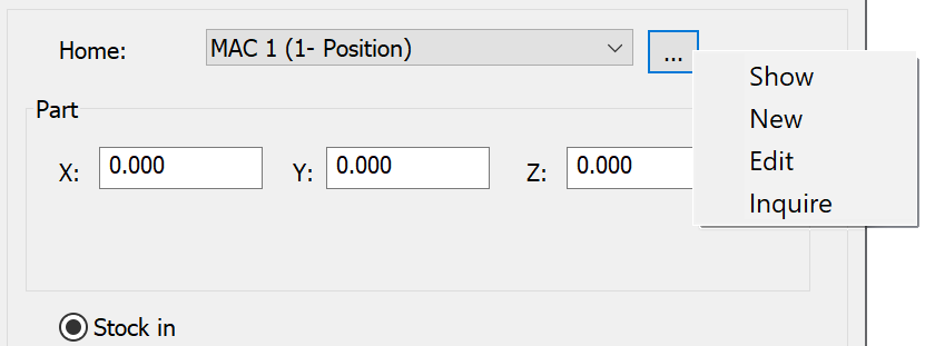
Clicking Table Position
displays the Home field. The Home
field displays the list of defined coordinate systems. Click ![]() to Show, New,
Edit
and Inquire
a CoordSys.
to Show, New,
Edit
and Inquire
a CoordSys.
8. In the Part field, the X,
Y, and Z coordinates define the part's origin position relative to the
Machine Coordinate System position. The X,Y,Z values can be defined as
well as chosen by clicking ![]() .
.
Click ![]() , to Pick
X, Pick Y, Pick
Z, Pick XYZ points directly
on the part. Selecting any of these options opens the Pick
Point dialog box.
, to Pick
X, Pick Y, Pick
Z, Pick XYZ points directly
on the part. Selecting any of these options opens the Pick
Point dialog box.
In machines without Tool Contact Point, you must set the part position exactly as in a real machine. It is essential for accurate mpos, rtpos, and rpos sets calculation. You must measure it on the machine and copy to the setup. Selecting Set absolute value allows you to automatically set the absolute value as is on the Machine for the Part or Fixture. Selecting this option displays the Absolute Value from Machine dialog box.
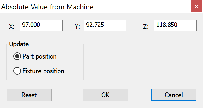
The Update Part position is set as default. Choose Update Part position to set the absolute value as is on the Machine for the Part or choose Update Fixture position to set the absolute value as is on the Machine for the fixture.
9. The Stock in option can be enabled by right-clicking Table name and Position number or, selecting the Table name and Position number.
10. Selecting Advanced enables you to define the rotary values for fixture and part.
11. Click the check box before the Table name in the tree view to display the fixture directly on the model.
When you complete the Setup definition by clicking OK, SolidCAM adds the Setup item to the CAM tree according to the chosen location. To manage an existing Setup, right-click the subheader and choose a command from the menu.
Machine Preview
The Machine Preview ![]() enables you to display the Machine Preview
dialog box to quickly visualize the schematic position of the machine
devices without entering the Machine
Simulation mode.
enables you to display the Machine Preview
dialog box to quickly visualize the schematic position of the machine
devices without entering the Machine
Simulation mode.
Skip machine limit warnings
When Skip machine limit warnings is selected, SolidCAM will not display any error messages when checking the machine limits in the GCode output or during the Machine simulation. This option can be activated by changing the settings in the VMID file of the CNC-Machine.