Geometry page
In this section you have to specify the contour, i.e. profile geometry that you want to engrave on the 3D model surface.
2D Engraving
If you choose the 2D Engraving strategy in the Technology section, you have to define a new geometry as in any other operation.
The geometry is similar to the Pocket geometry.
In the Text section of the Geometry Edit dialog box, click Add to start defining a text line. The Text definition dialog box is displayed.
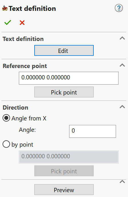
- In the Text definition section, click Edit. The Draw Tools dialog box is displayed.
- Click the
 button
to place the text frame. Type in the text line. Use other menu buttons
to define the text font, justification, direction, etc. Confirm the
dialog box with the
button
to place the text frame. Type in the text line. Use other menu buttons
to define the text font, justification, direction, etc. Confirm the
dialog box with the button.
The Text definition
dialog box is displayed again.
button.
The Text definition
dialog box is displayed again. - In the Reference point section, type in the coordinates of the text starting point or click the Pick point button and pick the point directly on the solid model.
- Specify the text line direction by an Angle from X or by point. This point can also be picked on the solid model. The direction is defined as a line going through the Reference point and this direction point.
- Click Preview to verify the line location on the model surface.
- Click
 to accept the text editing.
 When you have completed the geometry definition, confirm the Geometry Edit dialog box with the
.
3D Engraving
If you choose the 3D Engraving strategy in the Technology section, you have to specify both the contour, i.e. profile geometry that you want to engrave, and the 3D model.
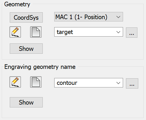
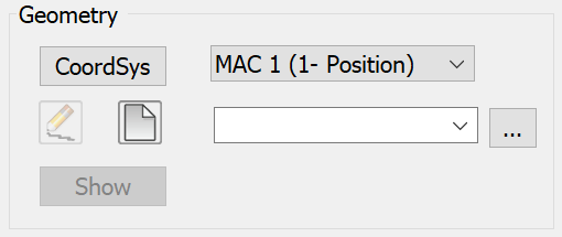
In the Geometry section, you have to define the 3D model geometry.
In the Engraving geometry name section, you can define the contour geometry in the same way as in the 2D Engraving strategy.