Select Faces dialog box
This dialog box enables you to define the parameters of the pocket feature recognition geometry.
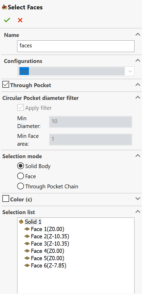
Name
This option enables you to define the name of the geometry. SolidCAM offers you the Default Geometry name that can be edited.
Configurations
This section enables you to select the SOLIDWORKS model configuration to be used for the geometry definition.
Through Pocket
When this check box is selected with the Selection mode set to Solid body, the recognition of through pocket features is also performed.
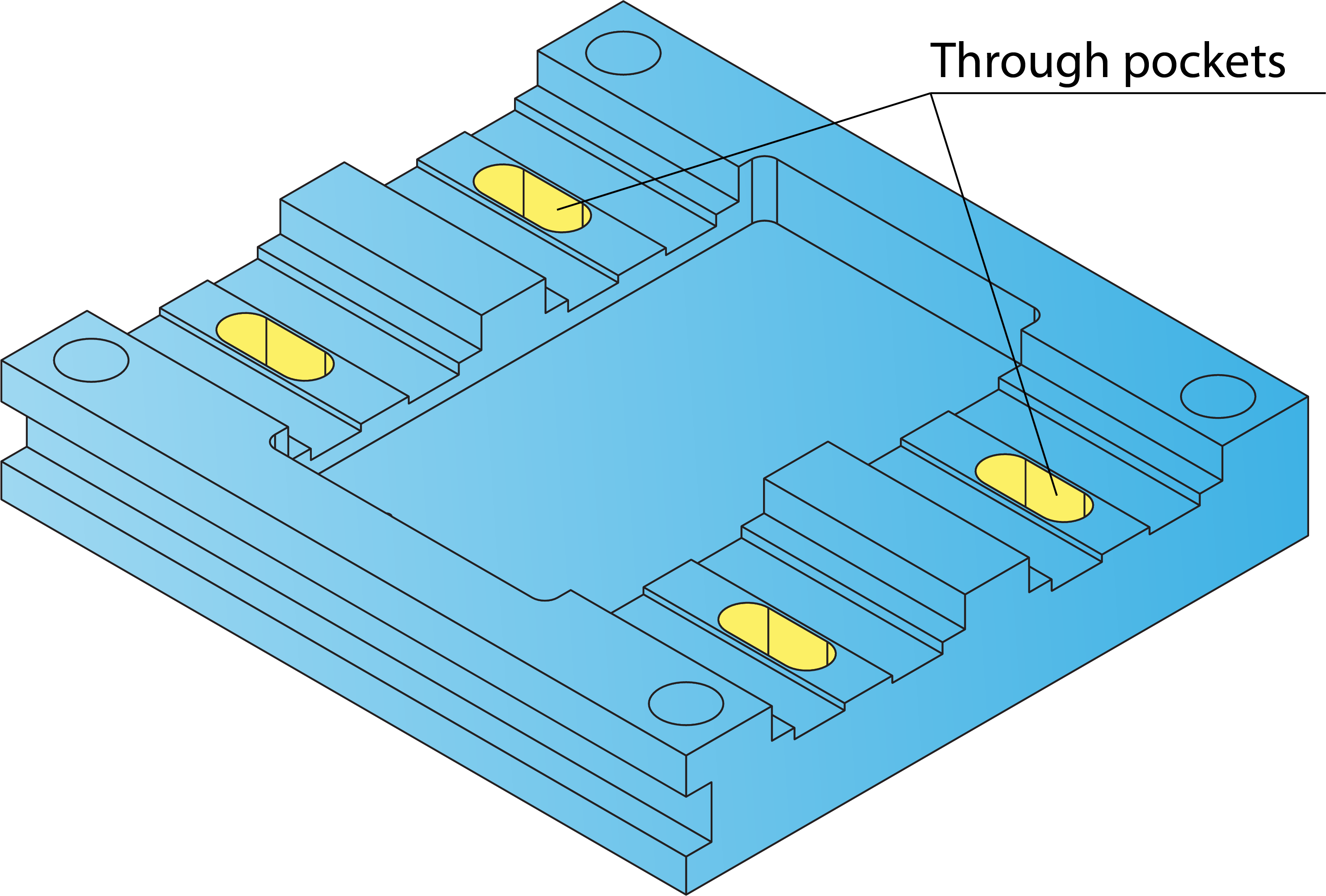
Only the through pocket features where the upper loop is similar to the lower loop are recognized. The through pocket features that cannot be machined with the current CoordSys position cannot be selected.
Circular Pocket diameter filter
When this check box is selected with the Selection mode set to Solid body, circular pocket features can be selected according to their diameter. All circular pocket features with the diameter greater than the specified Min. Diameter value will be selected. Using this option, you can avoid the machining of the drill features that are supposed to be machined in other operations (Drilling, Drill Recognition, etc.).
The Min. Diameter parameter defines the minimum diameter of the pocket features. You may enter the value in the edit box or pick a cylindrical surface or a circular edge in the solid model when the cursor is placed in the Min. Diameter edit box.
The Min. face Area parameter allows you to set the minimum face area of the pocket feature. When the value is specified, the area below the set value is not picked up for machining.
When the Apply filter check box is not selected, all recognized circular pocket areas suitable for the current Coordinate System will be selected.
Selection mode
This section enables you to set the mode of the geometry selection. The following selection modes are available:
This mode enables you to perform automatic recognition of the pocket features on the picked solid body. All planar faces are recognized with the surface normal vector oriented parallel to the Z-axis of the current CoordSys. The planar faces that cannot be machined with the current CoordSys position (undercuts) cannot be selected (the selection is rejected). All the through pocket areas are recognized according to the Through pocket option.
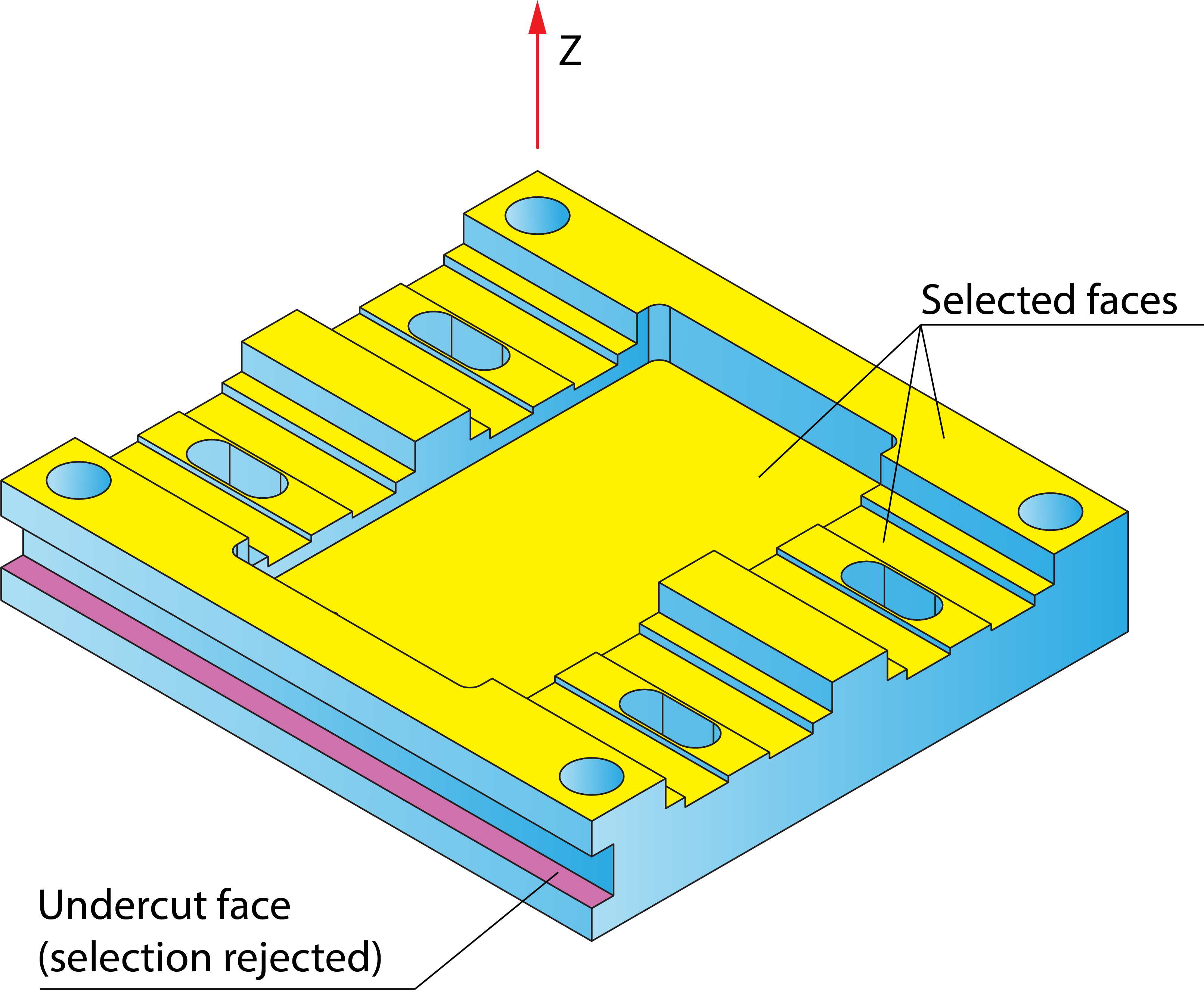
This mode enables you to pick single planar faces. When a face is picked, SolidCAM checks the parallel relation between the surface normal vector of the picked face and the positive direction of the Z-axis of the current CoordSys. If they are not parallel, the face is not selected. The undercut faces that cannot be machined with the current CoordSys position are also not selected. The selection is working in the toggling mode: the first click on a face selects it, the next click on the selected face removes the selection.
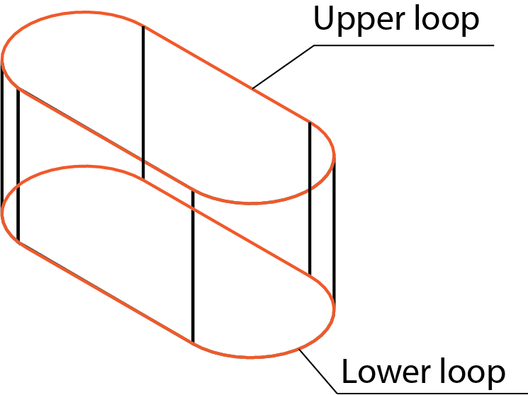
This mode enables you to select the through pockets by picking one of the edges of the lower loop of the pocket area. When the edge is picked, the complete geometry of the through pocket is automatically selected. The lower loop is highlighted on the model. The selection is working in the toggling mode: the first click on an edge selects the loop, the next click on an edge of the already selected loop removes the selection.
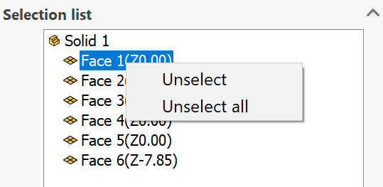
List of recognized elements
This section displays the list of all recognized model elements included in the geometry for the operation. Each model element is accompanied by its Z-level value enclosed in parentheses. When an element is selected in the list, it is highlighted on the solid model.
The right-click menu is available on the list items. The Unselect command enables you to remove the current item from the selected geometry. The Unselect All command enables you to remove the selection from all items in the list.