Geometry page
This page enables you to define the machining geometry for the operation.
Defining the geometry
The automatically recognized geometry consists of planar faces and loops of through pocket features. The definition of the geometry is performed in the Select Faces dialog box.
The major steps of the Pocket Recognition geometry selection are:
Choose the model configuration used for the recognition;
Set the selection filter options for Through Pocket and Circular Pocket;
Set the selection mode;
Perform the pocket recognition and generate the faces tree;
Choose the faces you want to include in the operation geometry.
|
Some small faces may not be included automatically in the geometry, if their area is less then Gap maximum * Gap maximum tolerance value defined in CAM Settings. These faces should be selected manually. |
When the Select Faces dialog box is confirmed, SolidCAM automatically generates a number of pocket contours to perform the optimal machining of the selected faces and through pockets.
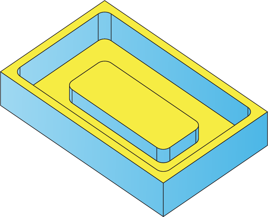
In the part shown below, the contours are generated from the selected planar faces.
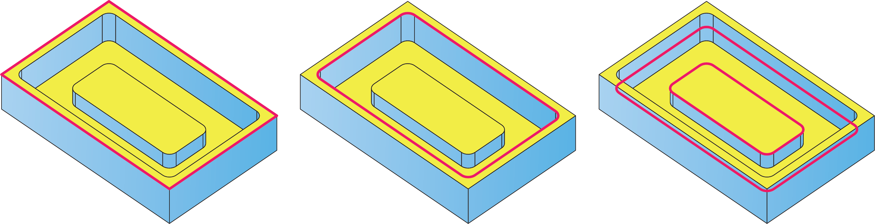
The machining is performed in the following sequence: first, the upper face is machined; then the pocket is machined up to the height of the central pad. From this height, the pocket with island is machined up to the final pocket depth.
Edit Geometry
After the geometry is defined, it can be shared between a number of Pocket Recognition operations. In each operation, SolidCAM enables you to perform a specific geometry modification. The modification is relevant only for the current operation and does not affect other operations based on this geometry.
The Modify button displays the Geometry Modify dialog box that enables you to define the parameters of the geometry modification.
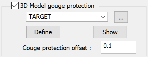
3D Model gouge protection
3D Model gouge protection uses the target solid model plus a specified offset to prevent a chain geometry from cutting into the target. This is very helpful for models having undercut features where you have selected the floor geometry but you have a overhang or ledge over that floor.
![]() displays the 3D
Geometry dialog box and enables you to define a new Target.
displays the 3D
Geometry dialog box and enables you to define a new Target.
![]() displays the defined Target
geometry on the SOLIDWORKS model.
displays the defined Target
geometry on the SOLIDWORKS model.
![]() displays the Browse Geometries
dialog box that enables you to visualize the geometry during the selection
process; the selected geometry is highlighted in the SOLIDWORKS
Graphics Area.
displays the Browse Geometries
dialog box that enables you to visualize the geometry during the selection
process; the selected geometry is highlighted in the SOLIDWORKS
Graphics Area.
Gouge protection offset field enables you to define a value by which the tool is moved away from the machining surface.
Fixture Collision Protection
Fixture Collision Protection automatically adjusts the tool path to avoid contact between your defined setup and the selected tool.
![]()
The Fixture clearance parameter defines the distance by which the tool can approach the setup during machining.
Related Topics