Technology page: Limits tab
A limit is a profile geometry that can be used to define additional 2D profiles on the surface and to exclude areas on the surface from machining.
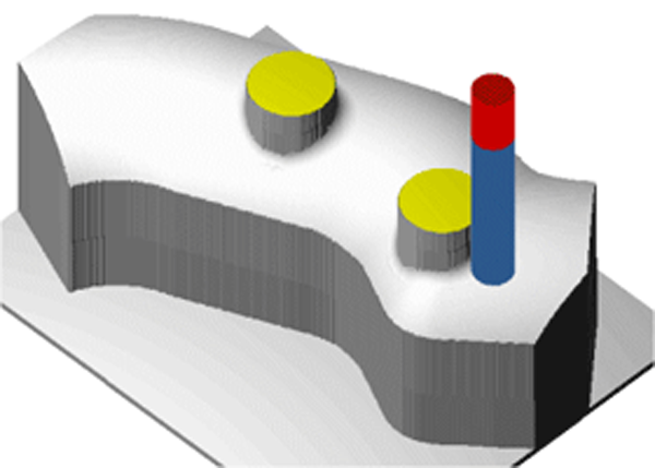
![]()
The geometries in the above example result in the following translated surface with limits:
The Limits tab is available only if the Use limits check box is selected on the Surface page.
Limit geometry name
In this section, specify which contour, i.e. profile geometry, you want to use as the Limit. Note that the Limit geometry must be closed.
Limit geometry offset
After machining, the CAM-Part will have remaining material on the limit geometry equal to this value.
Machining area
Outside Limit geometry
The area of the translated surface outside the limit is machined.
Inside Limit geometry
Only the area inside of the limit geometries is machined.
Finish on limit geometry
Select this check box if you intend to semi-finish and/or finish the limits on the translated surface.
Use the lists to select the cycles you want to perform.
Type
The Finish option machines the limit to its final dimensions in one step down.
The Semi-finish option prepares the limits to an offset specified in the Offset field with the cutting depth defined in the Step down field.
The Both option machines the limit with a semi-finish cut first and then with a finishing cut.
Side
If the Limit geometry is composed of one or more chains, but neither is placed inside another chain, the default option Both should be used. SolidCAM will then use the relevant finish side depending on whether the Limit type is Outside or Inside.
In this example, the Limit geometry contains a chain inside another chain (Chain #2 inside Chain #1) and a separate limit Chain #3.
![]()
- The External option finishes all outside contours of the Limit chains, leaving the inside hole unfinished.
![]()
- The Internal option finishes only the inside contour of the Limit chain, leaving the outside Limit contours unfinished.
![]()
- The Both option finishes all inside and outside contours of the Limit chains.
![]()
Cutting direction
This field defines the cutting direction on the last finish cut. It can be either clockwise (CW) or counterclockwise (CCW).
Semi-finish offset
Enter the offset that will remain on the surface after the semi-finish operation. This offset will be removed in a last cut, if a finish cut has been specified.
Semi-finish step down
The step down defines the cutting depth of the tool on the Limit geometries used for the semi-finishing operation.