Geometry page
Technology
The Translated Surface operation can be used to mill surfaces and also to engrave profiles, such as text, on a translated surface.
To engrave a profile on a translated surface, use the Translated Surface operation that you used to mill the surface as a template. Click Add Milling Operation, Translated Surface and select the original Translated Surface operation from the Operation name list in the operation dialog box. All the geometries and parameters of the original operation are copied.

Choose the Technology and continue defining additional parameters.
Geometry
This section enables you to choose the appropriate Coordinate System and to define the Machining Geometry for the operation.
Section geometry name
A translated surface requires two geometries: the profile along which
the section is translated and the section geometry.
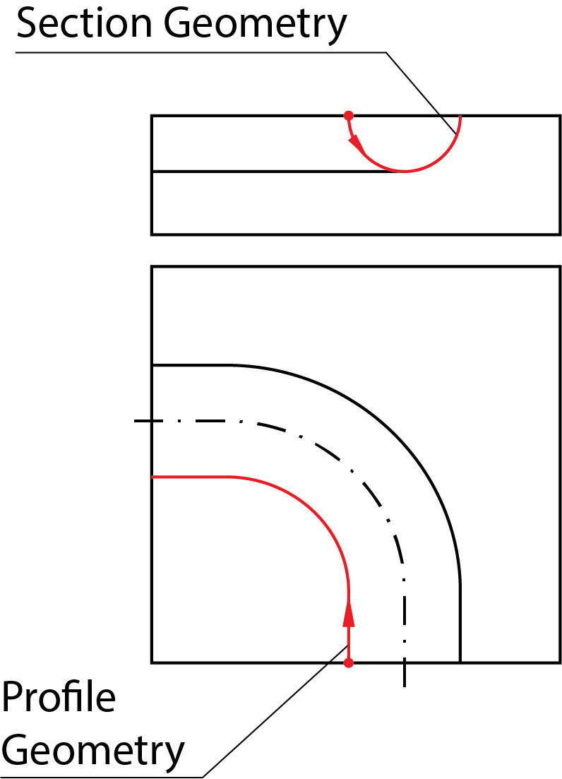
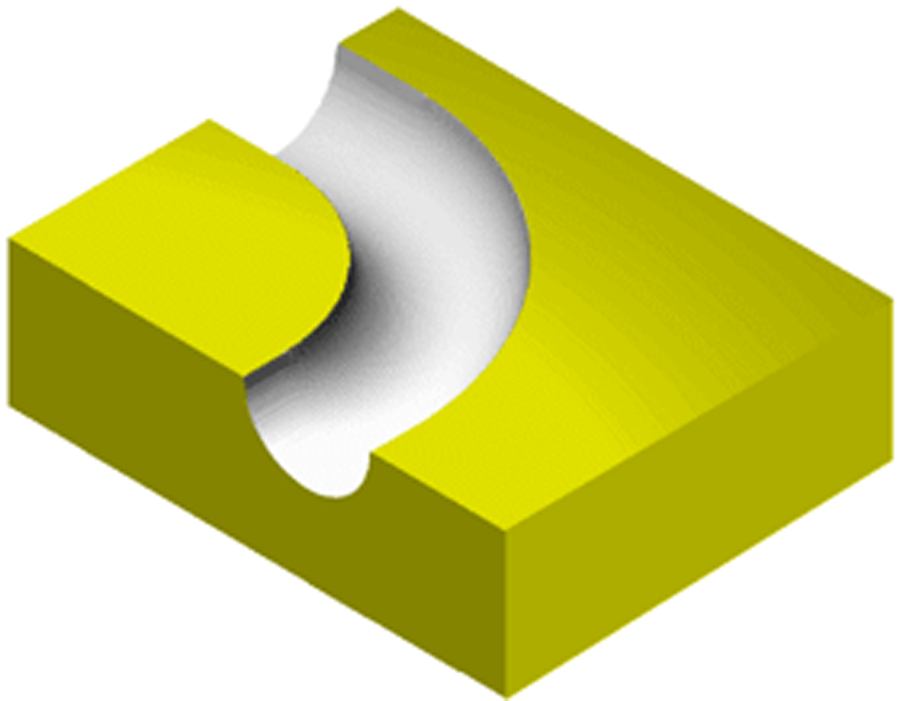
The geometries in the above example result in the following translated surface:
More...
Geometry on section
This option enables you to locate the section on the profile.
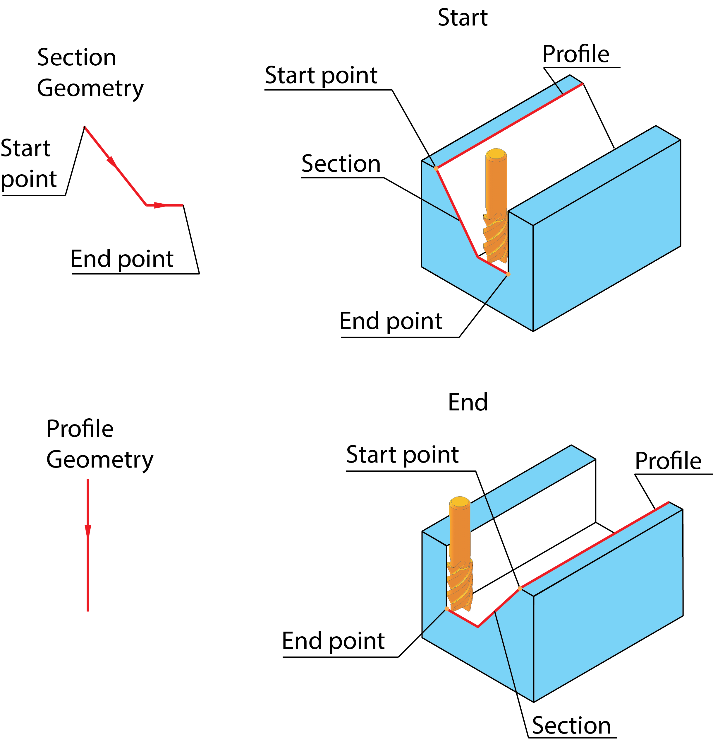
- Start: the profile geometry is located at the start of the section and the machining is performed from the start of the section towards the end of the section.
- End: the profile geometry is located at the end of the section and the machining is performed from the end of the section towards the start of the section.
Side from drive geometry
This option determines on which side of the drive geometry the section is machined.
- Right: the tool path is generated on the right side of the drive geometry.
- Left: the tool path is generated on the left side of the drive geometry.
Geometry
Clicking this button opens the Modify Geometry dialog box.
Depending on the type of geometry modification, one of the following icons will be displayed next to the Geometry button:
 – indicates that the
geometry has been modified, but no Offset modifications have been
made.
 – indicates that
Offset modifications have been made with positive values only.
 – indicates that
Offset modifications have been made with negative values only.
 – indicates that
Offset modifications have been made with both positive and negative
values.
|
When you hover the mouse pointer over the Offset modification icons, a screen tip displays up to the first ten modified chains and their specified offsets. |
Surface offset
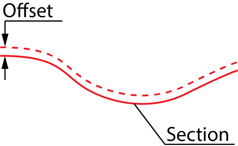
This value causes the final milled surface to be at an Offset from the defined surface.
