Passes Parameters for Combined Constant Z with Linear
The Passes tab displays the major parameters that affect the generation of tool path passes.
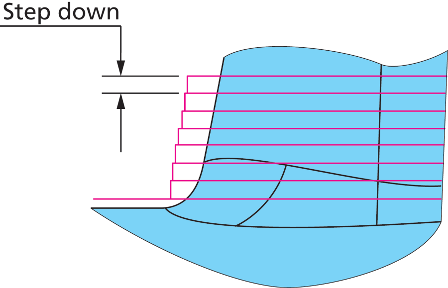
Step Down
| Step down This option allows you to define intermediate slices based on depth distance between them. When the Technology is selected as Combined Constant Z with Linear, the Step Down parameter defines the spacing of the passes along the tool axis. The passes are spaced at the distance set in the Step Down field. |
|
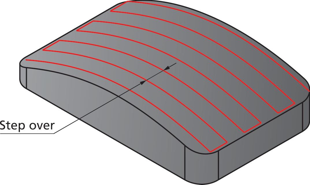
Step over
| Step over is the distance between two adjacent passes.
Maximum step over enables you to define the distance between two adjacent cuts. Scallop enables you to define the value to control the distance between the tool path lines by the cusp height you want to achieve on the finished model.
|
|
Define angle by
When you select the Optimal machining angle in X,Y check box, SolidCAM automatically defines the angle required for machining.
When Optimal machining angle in X,Y check box is not selected, the angle can be defined by entering its Value in the edit box or by picking a Line on the model.
Limits
The limits are the highest and lowest Z-positions for the tool – the range in which it can move
More
Shallow Areas
Angle limit is applied on shallow areas where the tool path is projected within the angle specified in the Angle limit field.
Continuous connection passes between two regions within the angle limit interval of 0°-85°. The best observation is near the vertical walls where the tool passes through different regions without any retracts.
Cut tolerance
The Cut tolerance parameter defines the tool path accuracy
Related Topics