Undercut Milling
Adding a Undercut Milling Operation
Overview
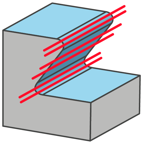
SolidCAM’s Constant Z Undercut Milling is a very powerful module for machining 3D components with tool path passes that are parallel to a plane depending on the machining direction. This is a strategy mainly used to semi-finish or finish steep areas of a component The step over is defined in the machining direction and is used to machine vertical or near vertical walls of a 3D component.
|
 |
Adding a Undercut Milling Operation
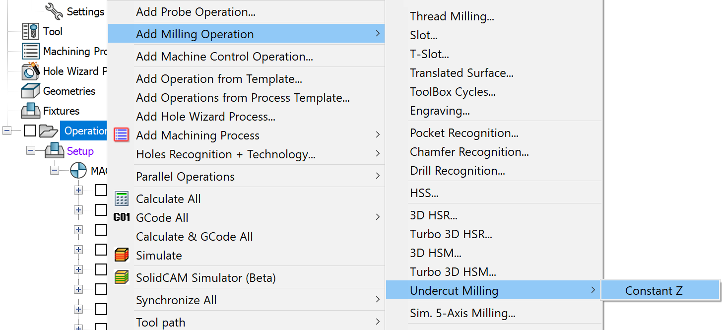
To add an Undercut Milling Operation to the CAM-Part, right-click the Operations header in CAM Manager and choose Undercut Milling > Constant Z command from the Add Milling Operation submenu.
The 3 Axis Undercut Machining dialog box is displayed.
Parameter pages
The parameters of the Undercut Milling operation are divided into a number of subgroups. The subgroups are displayed in a tree format on the left side of the Operation dialog box. When you click a subgroup name in the tree, the parameters of the selected subgroup appear on the right side of the dialog box.
Choose geometry for machining and define the related parameters.
Choose a tool for the operation and define the related parameters such as feed and spin.
Define the Clearance area and the machining levels.
Define the boundaries.
Define the passes parameters.
The Link and Default Lead-In/Out pages enable you to define how the Constant Z cutting passes are linked to the complete tool path.
The Gouge check and Clearance data pages enable you to avoid the tool gouging of any selected drive and check surfaces.
Define the parameters of the Undercut Machining.
Define the parameters related to the kinematics and special characteristics of your CNC-Machine.
Define a number of miscellaneous parameters and options related to the tool path calculation.