Using Drag & Drop Templates
There are different ways of using Drag & Drop templates.
Sr.No. |
Drag and Drop Template to.. |
Action |
||
1
|
|
Creates
an operation with the default MAC position and Level without any
Geometry. b. The Template Common Data dialog box is displayed. 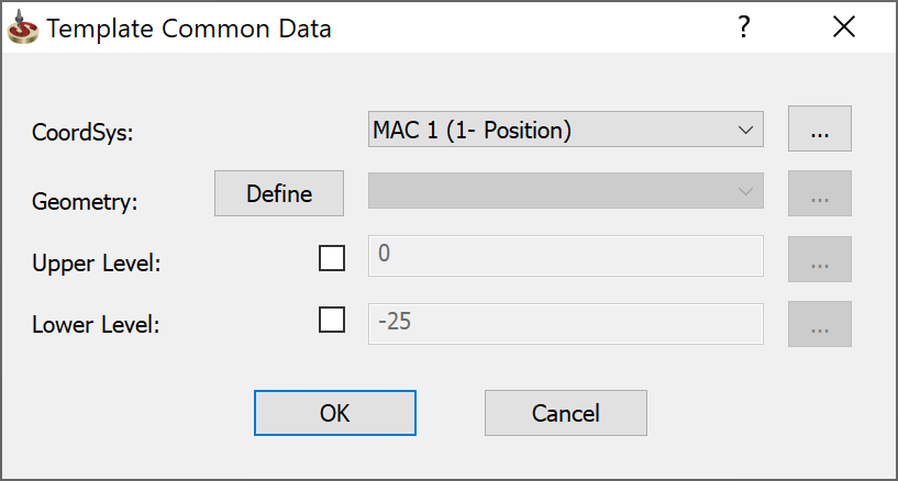 c. Select the home position
i. From the drop down list OR ii.
Click the CoordSys Manager dialog box. d. Select the Geometry i. From the drop down list OR ii. Click Define the Geometry Edit dialog box opens for editing OR iii. Click Geometries dialog box. e.
To edit the Upper Level Enable enable the check box OR click f.
To edit the Depth enable the check box OR click
g. An operation is created in the CAM tree. h. The operation is opened in Edit mode to complete the operation parameters. |
||
2 |
An operation with same MAC position and Geometry |
|
||
3 |
A face on the CAM-Part in HSS and Sim-5 Axis Operations | a.
Drag a template to the face.
b. The Template
Common Data
dialog box is displayed.
i. From the drop down list OR ii.
Click CoordSys Manager dialog box. d. Click OK to close the Template Common Data dialog box. e. The face geometry is created from the face (or faces) in the Drive surfaces field on the geometry page. f. The operation is opened in Edit mode to complete the operation parameters. |
||
4 |
A face on the CAM-Part in T-slot operation | a. Drag a template to the face. b. The Operation is created in the CAM tree with a copied Geometry, Tool, MAC Position and the Operation dialog box is displayed for editing. c. Define the Ceiling point for this Operation on the Levels page.
|
||
5 |
A face on the CAM-Part for remaining operations other than HSS and Sim 5-Axis operations | Creates an operation in the CAM tree with a copied Geometry, Tool and MAC Position. | ||
6 |
2.5D Milling operations where levels can be defined using one of the three alternatives- User defined, Top of Stock or Top of Target eg. Face, Pocket and Profile operations.
|
Creates an operation in the CAM tree with the following levels: User defined: If User defined is saved as level in the Template, it picks the value of face on which the Template is dragged. Top of stock: If Top of stock is saved as level in the Template, it picks the Top of stock value on which the Template is dragged. Top of target: If Top of target is saved as level in the Template, it picks the Top of target value on which the Template is dragged. |
||
7
|
Surface(s) of the CAM-Part | a.
Drag a template to the surface.
b. Before releasing the mouse button, hold the
control (Ctrl) button
on the keyboard and click on other surfaces.
c. After releasing the control button, the operation
is created in the CAM tree and all the surfaces are inserted under
a single geometry.
|
||
8 |
Drag & Drop a Process template | a. Face - An operation (or several operations) can be dropped on the face. When you drop a process template on a face the operations which have the relevant geometry will use the geometry else the operation is created in red color font which means the operation is incomplete and you have to select the geometry manually. b. CAM tree - All the operations from the Process Template are copied in the CAM tree and the geometries will have to be selected manually. c. Geometry - All the operations from the Process Template are copied in the CAM tree. | ||
9 |
a. Choose Single hole option to perform the process for only one selected hole. The operation is generated for that single hole only with respect to the CoordSys in the CAM tree. b. Choose Wizard option to select holes created in Hole Wizard. When you choose With Pattern, all holes created with Hole Wizard pattern are selected. The operations for all holes of same type are generated with respect to the CoordSys and hole type in CAM tree. c. The SOLIDWORKS HOLE
WIZARD is loaded by default. If you want to add a
new database click d. Drag
to Hole- Click e. Drag to Surface-
Click
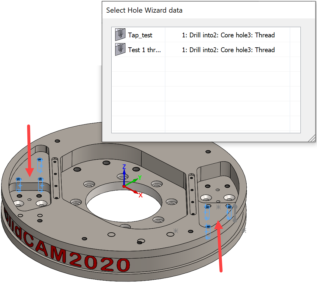
When using Drag & Drop templates with Hole recognition, SolidCAM highlights the features which will be processed next on the SOLIDWORKS model. The Select Hole Wizard data dialog box is displayed with the different variants of processes available enabling you to select the appropriate process.
|

Drag and Drop Operation(s)
Dragging and Dropping an Operation to a CAM-Part is similar to Dragging and Dropping a Template to CAM-Part.
The Operation which is dragged from the CAM-tree acts as a template when dragging and dropping to the face. A new Operation is created in the CAM-tree using the same Tool and Technology parameters.
If you grab several operations at the same time and drag and drop them to a face on the CAM-Part, you can create several operations in the CAM-tree. The operations which have the relevant geometry will use the geometry else the operation is created in red color font which means the operation is incomplete and you have to select the geometry manually.