Sim. 5-Axis Milling
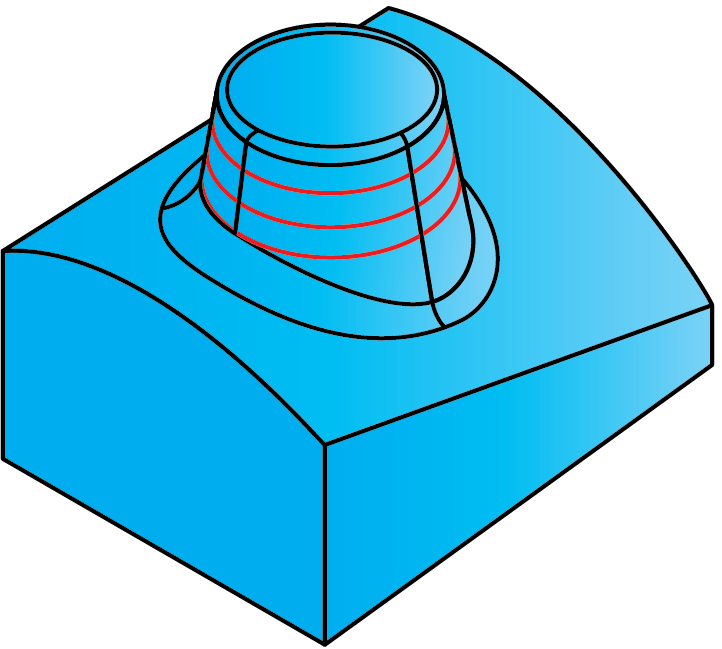
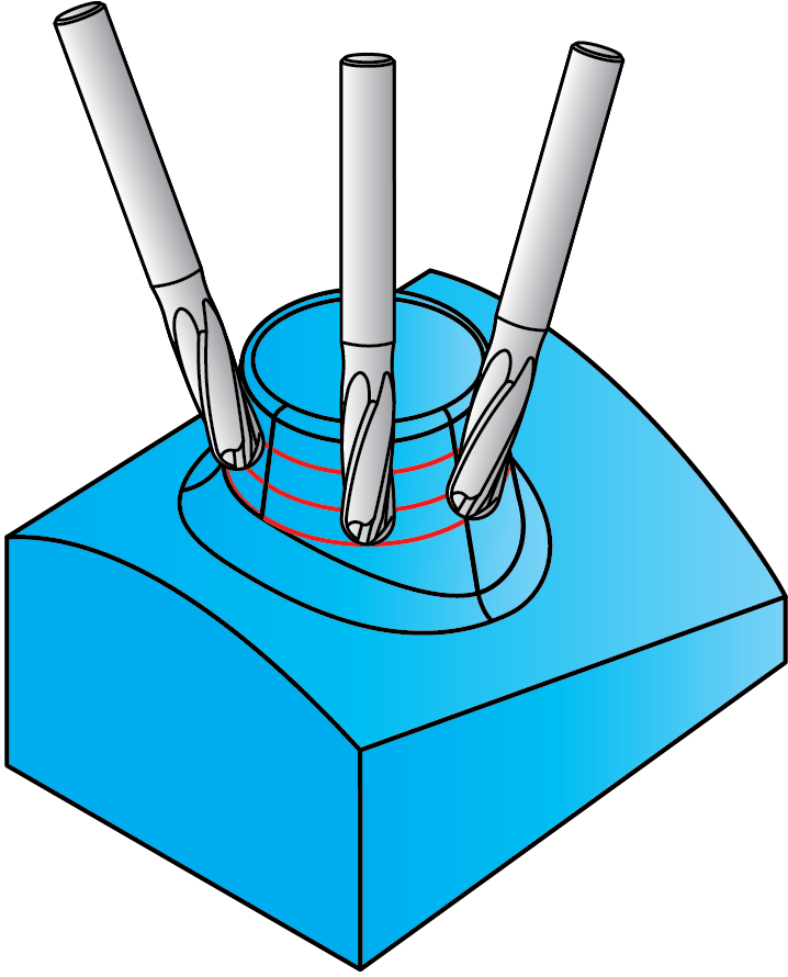
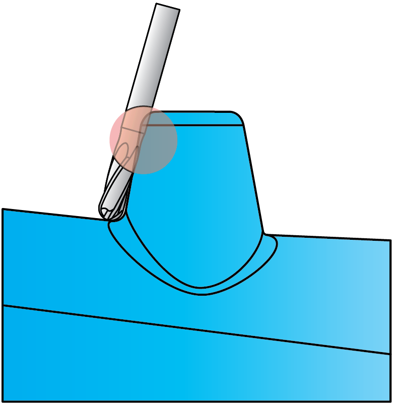
SolidCAM provides you with a number of Sim. 5-Axis operations designed for specific Sim. 5-Axis machining tasks. Each of these operations has a subset of parameters and options relevant for the chosen technology. Using the operations ensures quick programming of specific Sim. 5-Axis tasks.
Stages of the Sim. 5-Axis Operation parameters definition
Technology
SolidCAM provides you with the following types of the Sim. 5-Axis operation:
Parameter pages
The parameters of the Sim. 5-Axis operation are divided into a number of subgroups. The subgroups are displayed in a tree format on the left side of the Operation dialog box. When you click a subgroup name in the tree, the parameters of the selected subgroup appear on the right side of the dialog box.
CoordSys
Define the CoordSys position for the Sim. 5-Axis operation.
Geometry
Choose a geometry for machining and define parameters of machining strategy.
Tool
Choose a tool for the operation and define the related parameters such as feed and spin.
Levels
Define the Clearance area and the machining levels.
Tool path parameters
Define the machining parameters.
Tool axis control
Define the orientation of the tool axis during the Sim. 5-Axis machining.
Link
The Link and Default Lead-In/Out pages enable you to define how the Sim. 5-Axis cutting passes are linked to the complete tool path.
Gouge check
Avoid the tool gouging of the selected drive surfaces and check surfaces.
Roughing and More
Define the parameters of the Sim. 5-Axis roughing.
Machine control
Define the parameters related to the kinematics and special characteristics of the CNC-Machine.
Misc. parameters
Define a number of miscellaneous parameters and options related to the Sim. 5-Axis tool path calculation.
Stages of the Sim. 5-Axis Operation parameters definition
The operation definition is divided into three major stages:
|
 |
|
 |
|
 |