Conversion to Flat Cylinder Machinable Hole Feature segment
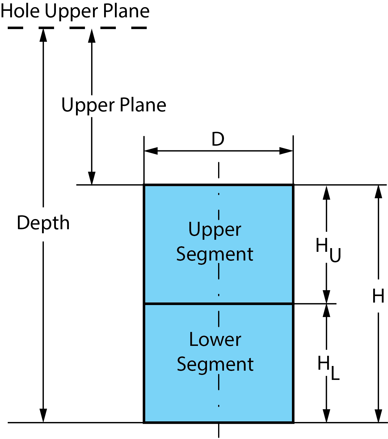
SolidCAM determines the following dimensions of the upper and lower Hole Feature segments of the pair. In the scheme below, the segments are represented as two cylinders surrounding the segments.
|
If the lower Hole
feature segment is Planar, the HL
is 0.
|
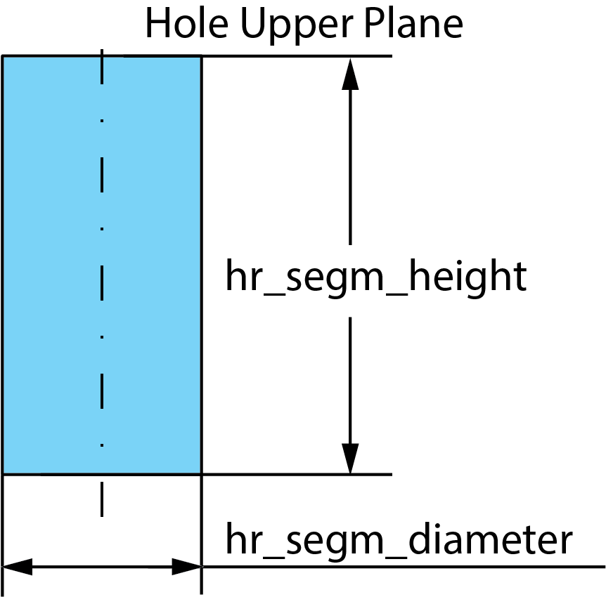
The scheme of Flat Cylinder Machinable Hole Feature generation is the following:
- The planar face is located on the same depth (hr_segm_diameter) as the lower point of the lower segment of the initial Hole Feature.
- The diameter of the Cylinder (hr_segm_height) is the same as the diameter of the Hole Feature Segment.
- The resulting segment is extended upward till the Hole Upper Plane.
Related Topics
- Conversion to Chamfer Machinable Hole Feature segment
- Conversion to Drill Machinable Hole Feature segment
- Conversion to Flat Chamfer Machinable Hole Feature segment
- Conversion to Reaming Machinable Hole Feature segment
- Conversion to Thread Machinable Hole Feature segment
- Machinable Hole Feature conversion