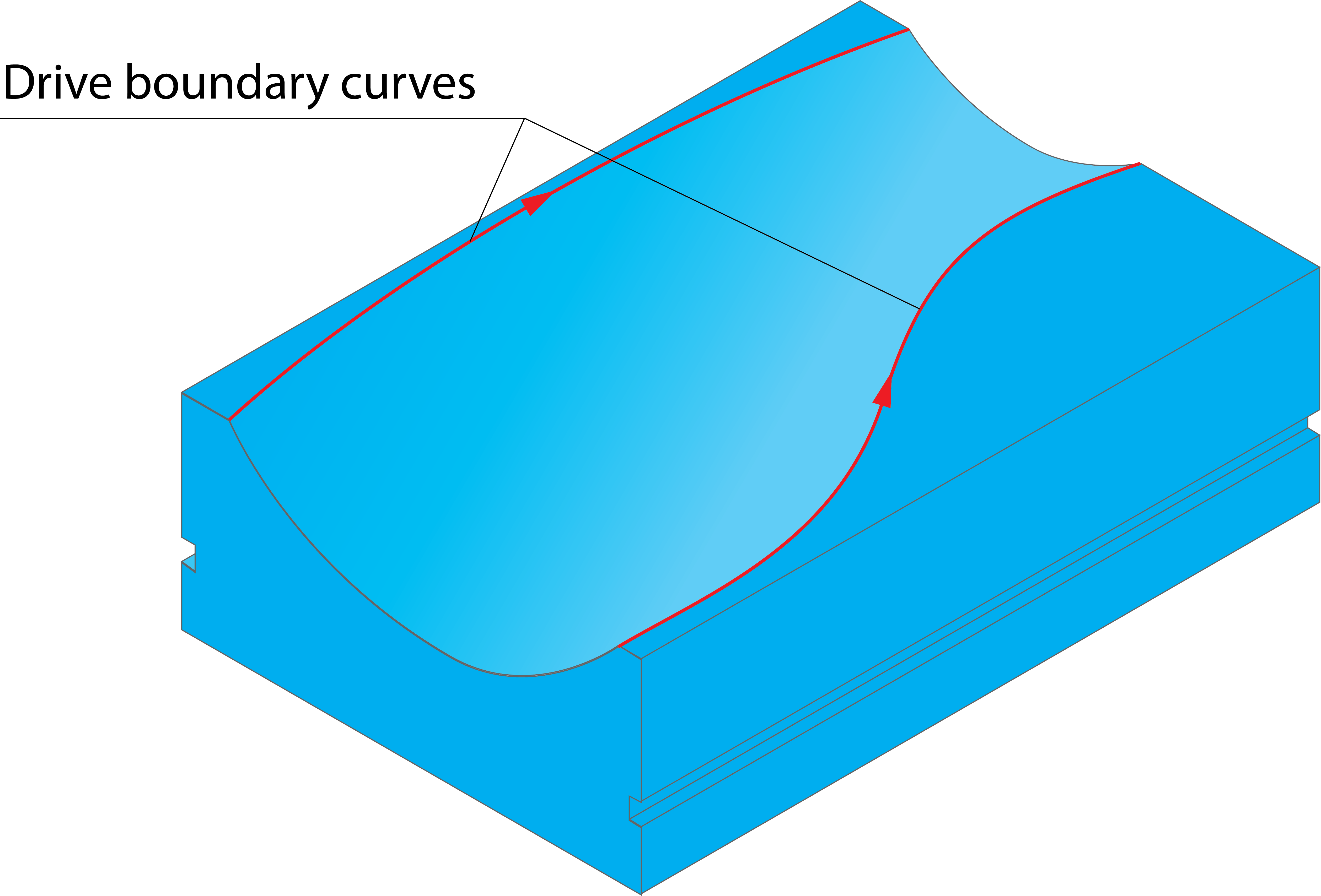
Drive boundaries for Morphed machining
SolidCAM enables you to define drive boundary curves for the Morphed machining strategy.
You can choose an existing geometries for the first and second drive curves from list or define a new one by clicking Define. The Geometry Edit dialog box is displayed.
The Show button displays the chosen drive curve geometry directly on the solid model.
|
Make sure that the directions of both drive curves are the same in order to perform the correct machining.
|
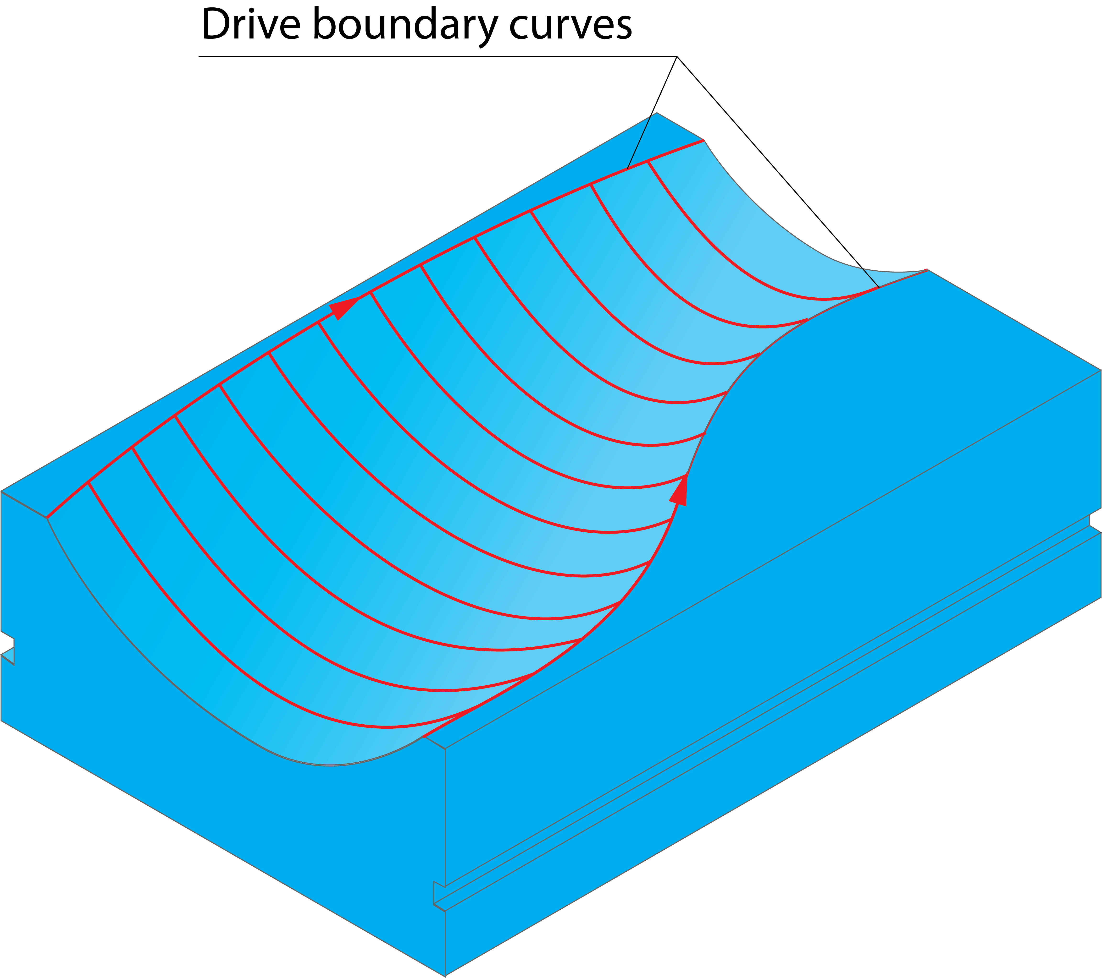
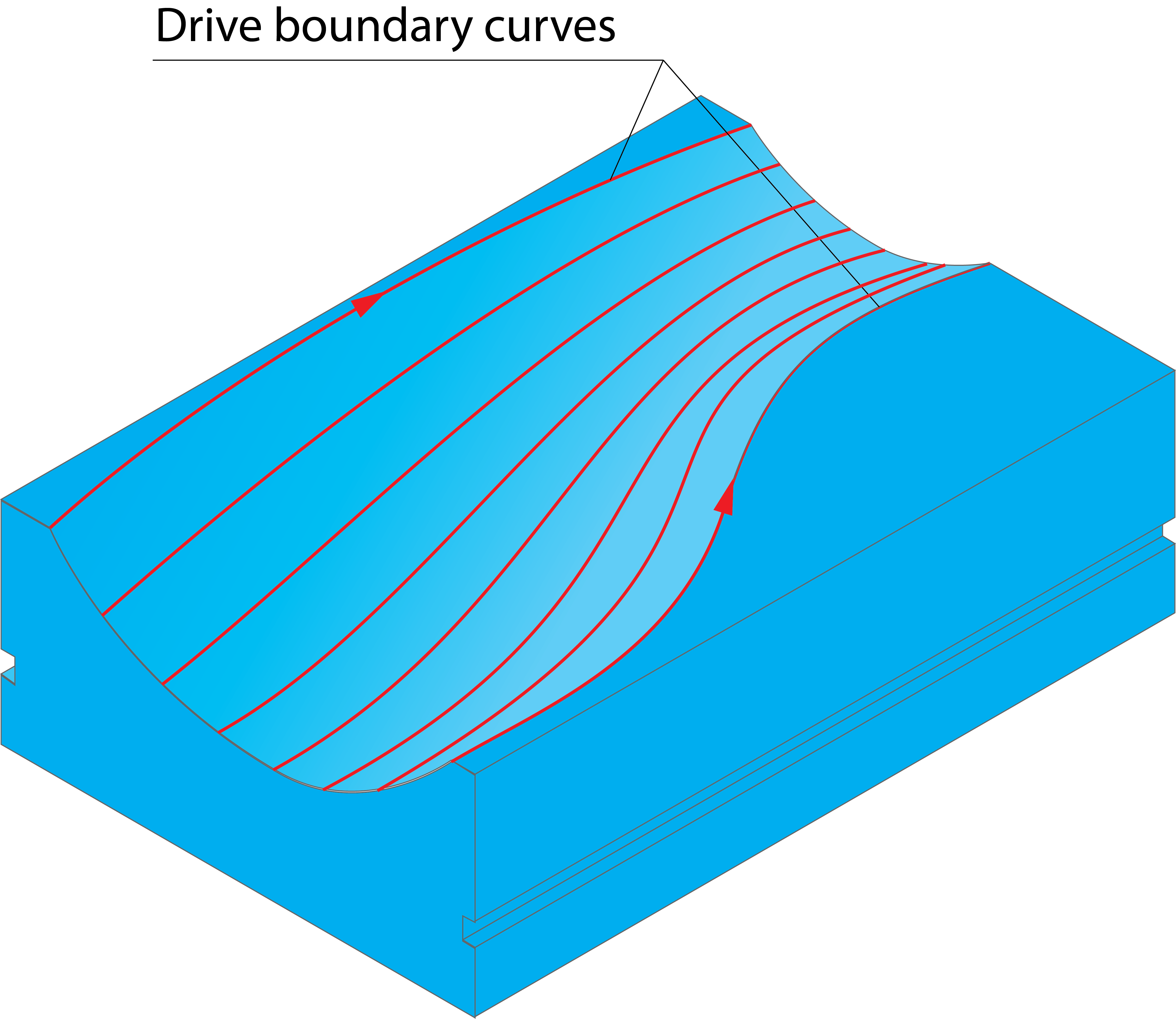
Cutting direction
This option enables you define the tool path direction between the drive curves.
Across- The morphed tool path is performed across the drive curves; each cutting pass connects the corresponding points on the drive curves.
Along- The morphed tool path is performed along the drive curves. The tool path morphs between the shapes of the drive curves gradually changing shape from the first drive curve to the second.
Boundary-Tool relation
The Boundary-Tool relation section enables you to define the position of the tool relative to the defined boundary and the related parameters.
Related Topics