Morphed machining parameters
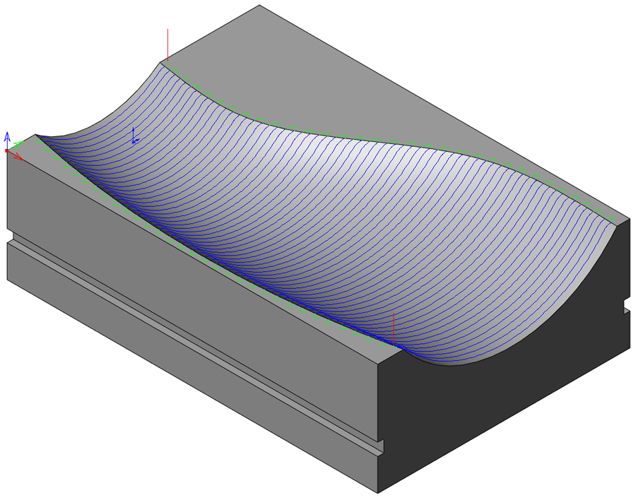
Morphed machining passes are generated across the model faces in a close-to-parallel formation, rather like Linear machining passes; each pass repeats the shape of the previous one and takes on some characteristics of the next one, and so the passes "morph" or gradually change shape from one side of the patch to the other.
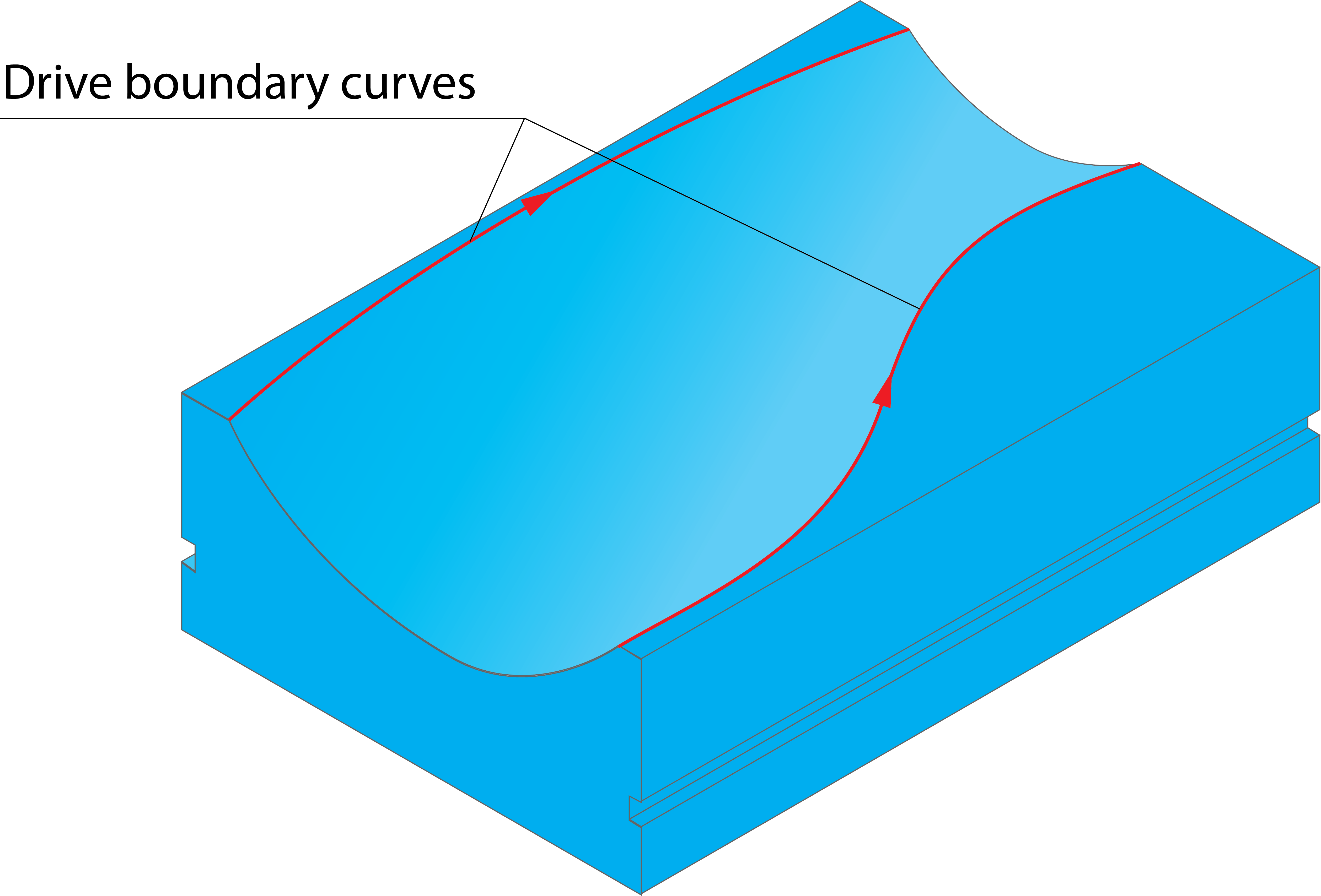
The shape and direction of the patch is defined by two drive boundary curves.
Step over
This parameter defines the distance between each two adjacent passes and is measured along the longest drive boundary curve. For the other drive boundary curve, the Step over is calculated automatically. For best results, the two drive boundaries should be as close in length as possible.
This machining strategy is most effective on areas that include shallow surfaces as the passes are spaced along the XY-plane (Step over) and not the Z-plane (Step down).
Related Topics
- 3D Constant step over machining parameters
- Contour roughing parameters
- Hatch Roughing parameters
- Helical machining parameters
- Linear machining parameters
- Offset cutting parameters
- Common Parameters
- Pencil Milling parameters
- Radial machining parameters
- Rest Roughing parameters
- Spiral machining parameters
- Strategy parameters