Rest Roughing parameters
The Rest roughing strategy determines the areas where material remains unmachined after the previous machining operations (the "rest" of the material) and generates a tool path for the machining of these areas. The tool path is generated in the Contour roughing manner. Rest roughing operation uses a tool of smaller diameter than that used in previous roughing operations.
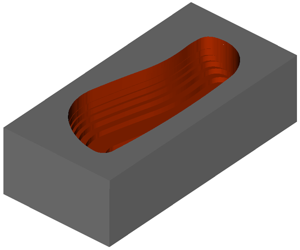
The following image illustrates the hatch roughing tool path performed with an End mill of Ø20.

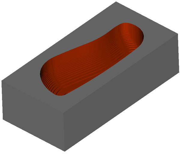
After the hatch roughing, a Rest roughing operation is performed with an End mill of Ø10. The tool path is generated in the contour roughing manner.
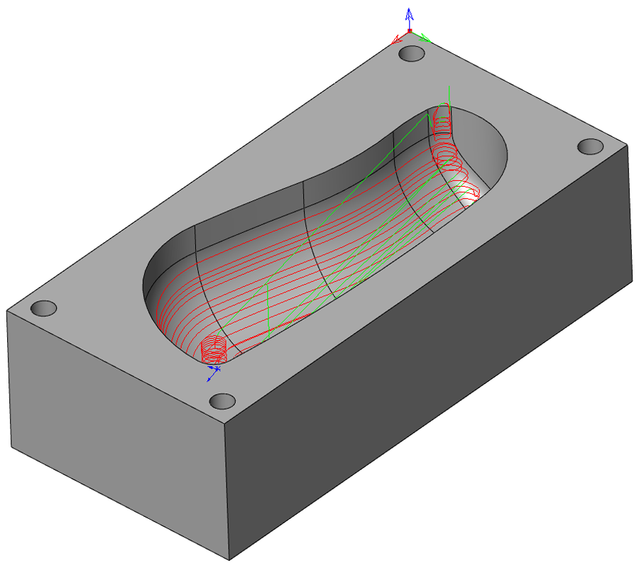
The Updated stock is generated automatically for rest material roughing calculation.
Detect Flat Areas
Detect Flat Areas inserts a tool path level on the flat area of the part and then carries the Z level slices at the programmed Z step. With Detect Flat Areas enabled, each stepdown is adjusted to match the flat areas such that the requested axial stock to leave is also the stock left in these areas.
Detect core areas
This option causes the tool to start from the outside of the model rather than take a full width cut in the center of the component.
If your model includes both core and cavity areas, the system will automatically switch between core roughing and cavity roughing within the same tool path.
When these passes are linked to create a Contour roughing tool path, the areas are machined from the top downwards. Obviously, material has to be machined at one level before moving down to the next one.
|
The passes for the Z-Top level machining are not usually included in the operation tool path. Adjust the Z-Top level by adding the Step down value to the current Z-Top level value when you want to include the top level passes in the operation tool path. |
Related Topics