Machine Database
The Machines tree of the iMachining Database dialog box enables you to add new and edit existing machine files contained in the iMachining Database. The current SolidCAM version includes a Machine Database Defined by VMID and Standard Machine Database.
Adding a new machine file to the iMachining Database
Adding a new machine file to the iMachining Database
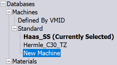
- Right-click Machines in the iMachining Database dialog box and select New Machine.
- By default the name of the new machine added is New Machine.
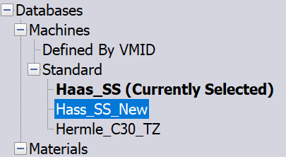
- Right-click New Machine and select Rename. Enter a name for the new machine file (e.g., Haas_SS_New)
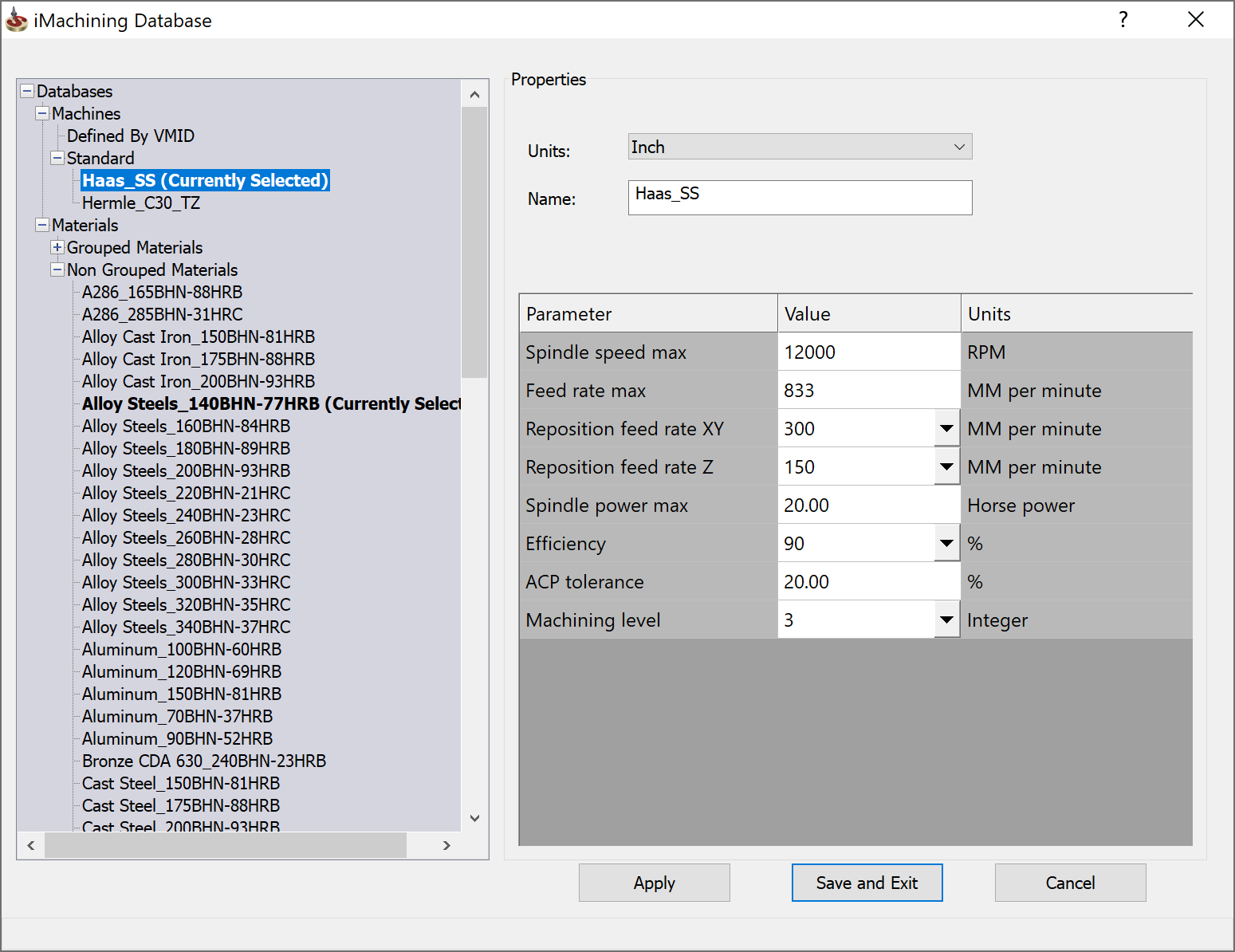
- There are three required values needed for the machine definition, which are represented by the highlighted fields.
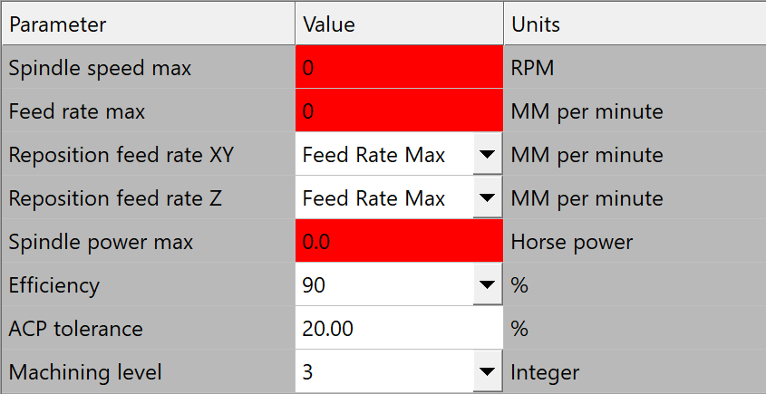
Spindle speed max, Feed rate max and Spindle power max reflect the machine parameters that are constant.
|
You can also add a New Machine by right-clicking Defined by VMID or Standard in the iMachining Machines Database to add New Machines in the respective categories. Right-clicking on Machines and adding a New Machine by default adds the New machine in the Standard Machines category. |
Defined by VMID
In SolidCAM 2019 and earlier versions, we could define Standard Machines only having constant machine parameters. In Mill-Turn machines, these parameters vary when you have two or more Submachines or active tool part cutting pairs. Added to the iMachining Database is the new machines category Defined by VMID that supports the varying parameters and VMID kinematics of two or more Submachines.
Right-click Define by VMID in the machines list to add to its category a New Machine. In the properties, all the machine related parameters are now set to 100% of the VMID values. Every iMachining operation, upon selecting the tool, can now be given the exact values of the specific Submachine being used which in turn provides the appropriate Cutting conditions calculations.
For specifically iMachining, the Define by VMID feature takes the values from the Machine Definition. iMachining determines which Submachine is being used and sends the correct values to the operation. iMachining also handles the sending of correct values to operations that can be performed simultaneously on Mill-turn machines having multiple channels. This feature can be used to create Machine entries in the iMachining Database for your most complex Mill-turn machines. Furthermore, this new feature simplifies overall the machine database definition and selection requirement for iMachining. In some cases, it may be possible to create just one new machine and name it eg. Global Machine. A Global Machine entry could be quickly and easily paired with any CNC-Machine whether it be a Mill-turn or Milling machine making for just a single selection in the Machine Database drop-down list of the CAM-Part definition.
Properties
Units: This option enables you to toggle the parameter values between Metric and Inch.
Name: The name of the machine selected is displayed in this field.
Parameters
This section enables you to define the general machine parameters.
| Spindle Speed Max | defines the maximum rated frequency at which the spindle can rotate, measured in revolutions per minute (RPM). | ||
| Feed Rate Max | defines the maximum rated velocity at which the cutter is advanced against the workpiece, measured in units of distance per time (MM/Min (Inch/Min)). | ||
| Reposition Feed Rate XY | defines
the feed rate for reposition moves when down in the cut.
|
||
| Reposition Feed Rate Z | defines the feed rate for the Z-down movements and the helical reposition moves when down in the cut. | ||
| Spindle Power Max | defines the maximum rated output power of the spindle, expressed in Kilowatts (Kw (Horsepower (Hp)). | ||
| Efficiency | defines the effectiveness of the motor in transmitting power to the spindle, specified in percentage (%). The drop-down list contains two typical motors available for selection:
If necessary, an Efficiency value can be entered manually. |
||
| ACP Tolerance | You can set a preferred percentage used to determine whether or not the displayed ACP value is favorable (highlighted in green = good). The ACP % parameter defines the tolerance for controlling the ACP indication and how the iMachining Technology Wizard outputs the depths. If the tolerance was set to 0, the Wizard would output an increased No. steps with a shallower Step down. With a higher tolerance, on the other hand, the Wizard will output a reduced No. steps with a deeper Step down. For new machines, the ACP tolerance is set to 20% by default. With this tolerance, the ACP indication will show that the situation for stability is good if you get a value of 1.1, 1.2, 1.8 or 1.9 for example.
|
||
| Machine Default Level | The Machining level parameter defines the default level of the machine according to its basic rigidity and state of maintenance. The assigned level is not to be influenced by the speed, power or acceleration capabilities of the machine. This level should only reflect the machine's tendency to develop vibrations.
The Machine Default Level is defined only once and is stored in the *.MACdbx file with all the other machine parameters (Spindle Speed Max, Feed Rate Max, etc.). This level only needs to be updated every 2-3 years, and after a crash or major maintenance procedure. |