Section depth type
Modify
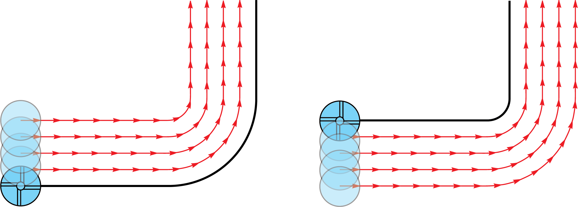
Tool side
Specify the side of the slot profile at which you want to mill. The tool side is always relative to the direction of the slot's chain geometry.
- Right: the tool machines on the right side of the slot geometry. The cut leaves material on the profile equal to the specified Profile offset value.
- Left: the tool machines on the left side of the slot geometry. The cut leaves material on the profile equal to the specified Profile offset value.
- Center: the center of the tool moves on the profile geometry.
|
When the Zigzag option is used, the Tool side combo-box defines the tool location for the first cut. For each successive cutting pass, the tool position is changed relative to the geometry direction.
|
Geometry
Clicking this button opens the Modify Geometry dialog box.
Depending on the type of geometry modification, one of the following icons will be displayed next to the Geometry button:
 – indicates that the
geometry has been modified, but no Offset modifications have been
made.
– indicates that the
geometry has been modified, but no Offset modifications have been
made. – indicates that
Offset modifications have been made with positive values only.
– indicates that
Offset modifications have been made with positive values only. – indicates that
Offset modifications have been made with negative values only.
– indicates that
Offset modifications have been made with negative values only. – indicates that
Offset modifications have been made with both positive and negative
values.
– indicates that
Offset modifications have been made with both positive and negative
values.
|
When you hover the mouse pointer over the Offset modification icons, a screen tip displays up to the first ten modified chains and their specified offsets. |
Section geometry name
The section specifies the depth profile for this slot operation. As the geometry for this 2.5D operation is designed using 2D profiles and sections, a reference point is required to indicate the position of the Upper level.
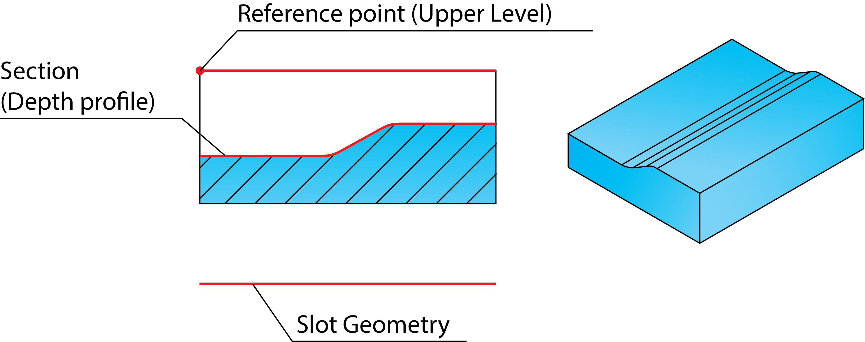
More about Section geometry...
Section data
This value determines the quality of the resulting surface on the floor of the slot. The smaller the value, the smoother is the surface.
Clear offset
With additional parameters for the right and left offset, the Center option enables you to clear offset and machine slots that are wider than the tool diameter. The given Step over value is used to cut from the right to the left side. Note that the side definition is always relative to the direction of the slot profile. Check the direction of the profile by clicking Show in the Section geometry name area of the Slot Operation dialog box.
- Right offset: enter the distance by which the slot is extended to the right side (relative to profile direction).
- Left offset: enter the distance by which the slot is extended to the left side (relative to profile direction).
- Step over: enter the step over in successive tool paths.
Offset
The Profile offset value specifies the offset that remains on the slot machined with the right or left tool side.
The Floor offset value specifies the offset that remains on the slot after the rough and semi-finish operations. This offset is removed in the last finish cut.
Rough, Semi-finish and Finish cycles
If you check this option, the rough operation clears the slot before the semi-finish operation is performed.
Enter the Step down between two successive cuts during roughing.
Define the offset that remains on the slot walls and floor after the roughing cut in the Rough/Semi-finish offset field.
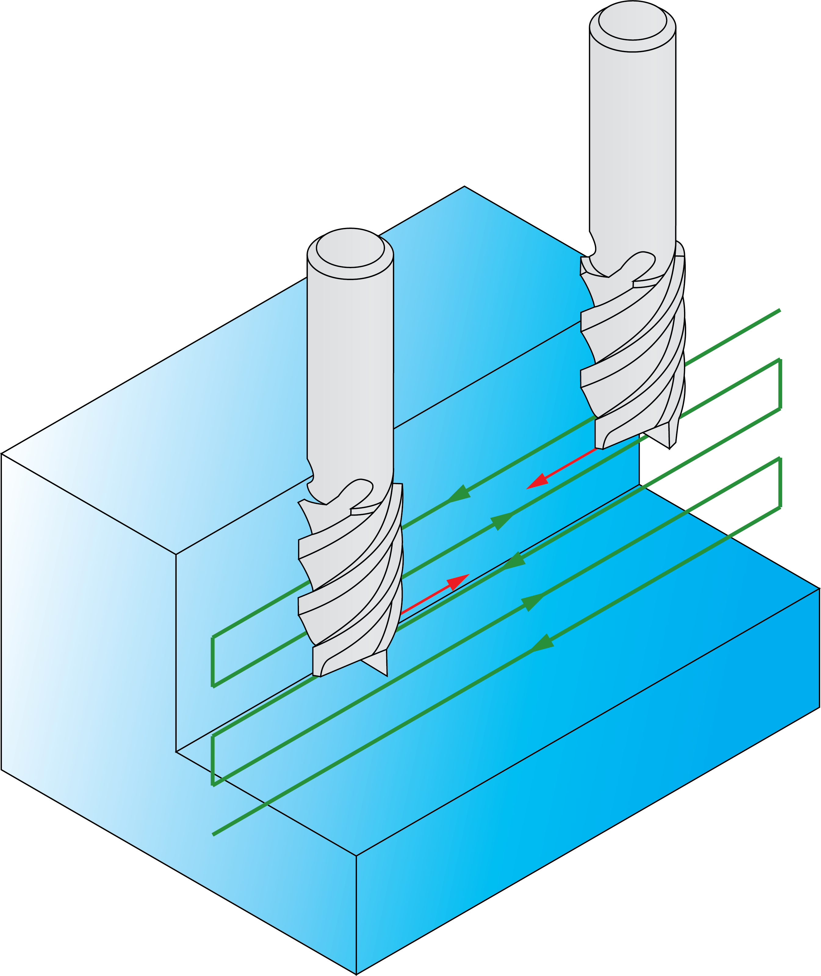
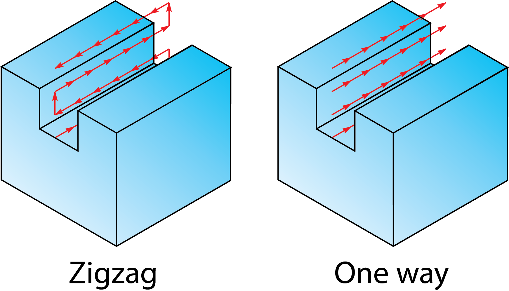
Cutting direction
The One way option enables you to create the tool path with only one-directional movements.
The Zigzag option enables you to create the tool path with bi-directional movements.
Check this option if you intend to semi-finish and/or finish the slot.
Choose the cycles you want to perform from the list.
- Semi-finish: the slot is machined at the offset specified in the Rough/Semi-finish offset field.
- Finish: the slot is machined to its final dimensions and specified surface scallop.
- Both: the slot is machined first with a semi-finish and then a finishing cut.
Related Topics