Simulation menu
This menu is common for SolidVerify and Quick SolidVerify simulation modes.
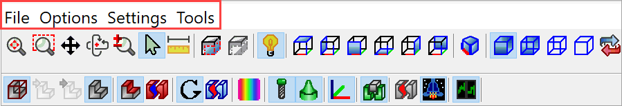
File
The Open machined stock from FCT option enables you to load the machined stock model from the SolidCAM FCT file (*.fct).
The Open machined stock from STL option enables you to load the machined stock model from the Stereolithography file (*.stl).
The Save machined stock to FCT option enables you to save the machined stock model to the SolidCAM FCT file (*.fct).
The Save machined stock to STL option enables you to save the machined stock model to the Stereolithography file (*.stl).
Options
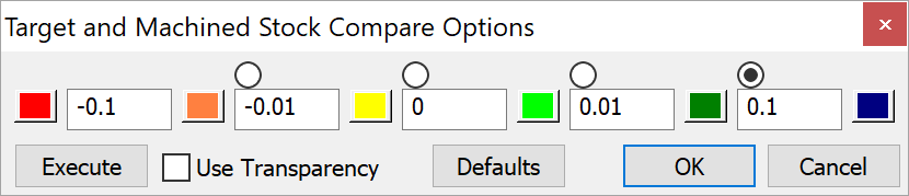
This option enables you to compare the machined stock model and target model and assign different colors to different rest material areas, depending on the value of the difference between the machined stock model and the target model.
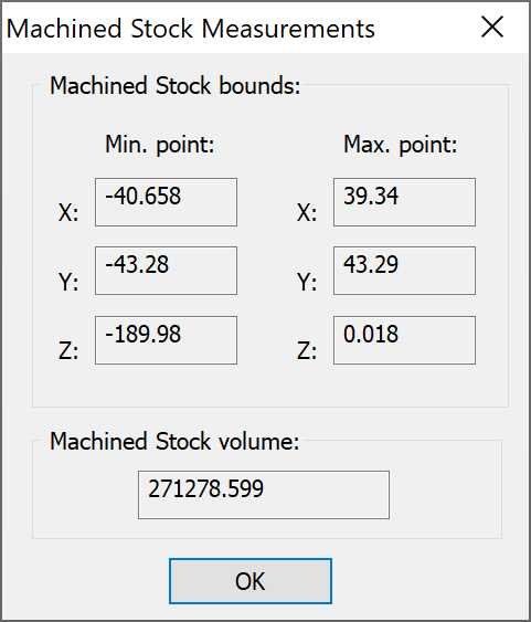
This option displays the Machined Stock Measurements dialog box where you can see the dimensions and the volume of the Machined stock model.
|
This option is available only in the SolidVerify simulation mode. |
This option displays the Region of interest dialog box that enables you to set the boundaries of the area you need to watch closely.
Disable region of Interest
This option disables the partial display mode.
Settings
This option enables you to define colors and transparency for the simulation. The Visual Properties dialog box is displayed.
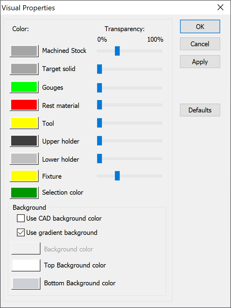
The Use CAD background color check box enables you to apply the simulation background color provided by the CAD system.
The Use gradient background check box enables you to apply the gradient background to the graphics area. Specify colors for Top Background color and Bottom Background color.
This command displays the View Settings dialog box that enables you to manage the settings of model rendering in the Quick SolidVerify simulation mode.
|
This option is available only in the Quick SolidVerify simulation mode. |
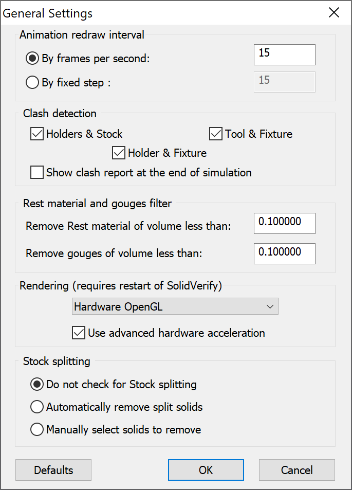
The By frames per second option enables you to expedite the simulation by defining the number of animation frames until the next redraw of the display.
The By fixed step option enables you to expedite the simulation by defining the number of tool movements until the next redraw of the display.
SolidCAM enables you to check the possible collisions between different components participating in the machining (tool, tool holder, machined stock model and fixture) during the simulation.
Holders and Stock – this option enables you to check the possible collisions between the tool holder and the machined stock model.
Tool and Fixture – this option enables you to check the possible collisions between the tool and the fixture model.
Holders and Fixture – this option enables you to check the possible collisions between the tool holder and the fixture.
Show clash report at the end of simulation - this option enables you to display a list of crashes at the end of simulation. If this option is not selected, each collision is reported in a separate warning message.
Rest material and gouges filter
Remove Rest material of volume less than: SolidCAM enables you to define the tolerance of the Rest material visualization.
Remove gouges of volume less than: SolidCAM enables you to define the tolerance of the gouge areas visualization.
|
These options are available only in the SolidVerify simulation mode. |
The functionality is implemented to improve the simulation performance with different graphic adapters. The OpenGL rendering options enable you to switch between the software/hardware OpenGL acceleration.
Software OpenGL – this option disables the OpenGL hardware capabilities and enables graphics rendering using software only. For many graphic cards, this results in slower performance. Select this option only if instructed to do so by technical support. This option enables you to solve the visualization troubles if your graphic card does not support hardware acceleration, or does not support it for the current combination of resolution, number of colors, refresh rate, and so forth.
Hardware OpenGL – the hardware OpenGL provided by your graphics adapter is used. The Use advanced hardware acceleration option enables you to use hardware acceleration provided by your graphic adapter.
Direct X - this option is used for rendering during simulation with some graphic cards.
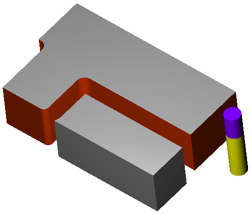
During the machining, the tool cuts off the material pieces. These pieces fall down from the machining area. This option enables you to automatically determine and remove such material pieces.
|
This option is available only in the SolidVerify simulation mode. |
The Stock splitting options enable you to control the process of automatic removal of cut off pieces.
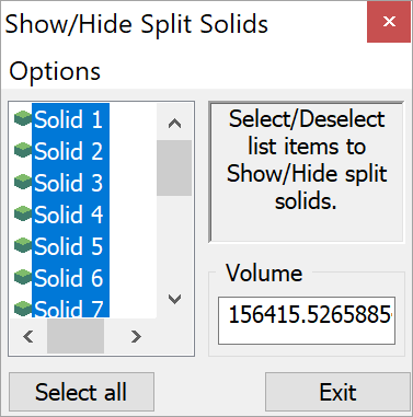
When this option is chosen, SolidCAM does not check the simulation solid model for splits. The cut off material pieces can be hidden or removed manually using the Show/Hide Split solids dialog box by clicking Split Gouges.
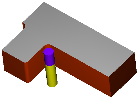
When this option is chosen, SolidCAM automatically determines stock splitting. When the split is determined, SolidCAM compares two resulting solids and automatically removes the smaller one.
When this option is chosen, SolidCAM automatically determines stock splitting and the following message is displayed:
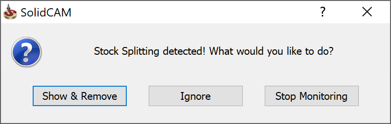
Show & Remove. The simulation is paused, and the Show/Hide Split solids dialog box is displayed. This dialog box enables you to hide or remove the cut off material pieces.
Ignore. The simulation is continued till the next split is determined. When the simulation is finished, the Show/Hide Split solids dialog box is displayed. This dialog box enables you to hide or remove the cut off material pieces.
Stop monitoring. The simulation is continued until the end without monitoring of splits.
|
This option is available only in the SolidVerify simulation mode. |
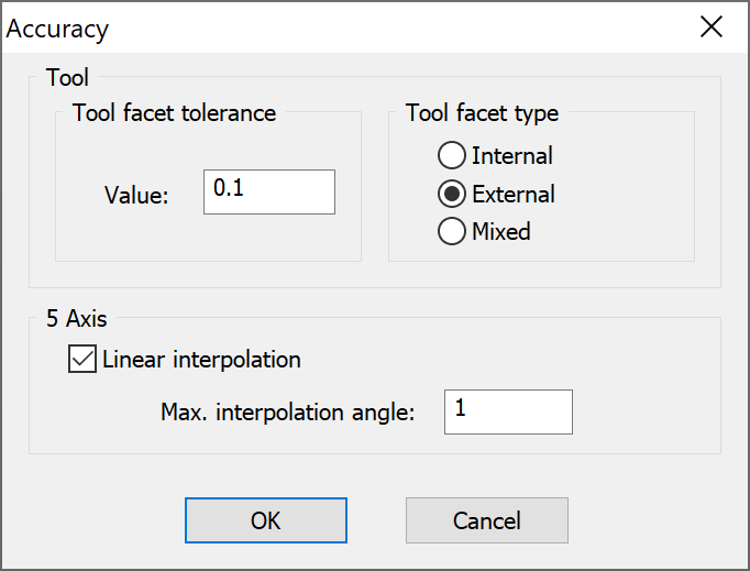
This option controls the precision of the tool for the simulation. The value defines the precision of the tool facets in millimeters or inches. Since this is an absolute value, the facet tolerance for small and large tools is the same. During the simulation, SolidCAM produces the Boolean subtraction of the tool from the CAM-Part.
The tolerance affects the quality of the simulation. The quality of the simulation is the same for large and small tools. The speed of the simulation depends on the tool. The simulation of larger tools is slower.
As well as changing the tolerance used for faceting, the application controls the manner in which the faceted tool representation approximates the tool by forcing the representation to be bigger or smaller than the actual tool. For example, if you want to know whether the tool gouged the target part, then it would be preferable for SolidVerify to have a tool representation that was guaranteed to lie outside the bounds of the actual tool.
Internal – the tool representation lies within the actual tool. The vertices of the tool representation lie on the surface of the actual tool and the facets lie within the actual tool.
External – the actual tool lies within the tool representation. The vertices lie at distances up to the faceting tolerance from the surface of the actual tool.
Mixed – this is a combination of Internal and External. The vertices lie outside the actual tool but parts of the facets may lie inside it. This mode is the default and should be used unless there is a specific reason for using one of the other modes as it generates fewer facets and is therefore faster.
The Linear interpolation option enables you to perform the linear interpolation of 5-axis tool movement. The Max. Interpolation Angle value defines the angular tolerance for the interpolation.
This option enables you to delete all the Updated Stock model files of the current CAM-Part.
|
This option is unavailable in the Manual mode. |
Tools
Self-intersections
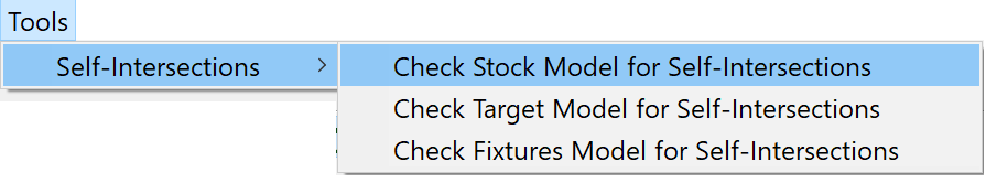
Many problems occur in simulations if the used solids (Machined Stock model, Target model or Fixture) are not topologically valid. In particular, in these simulation modes you are likely to encounter problems with solids that contain self-intersections – pairs of overlapping polygons or individual polygons with crossing edges.
Self-intersections can be encountered in the following cases:
The model (Stock, Target or Fixture) is based on a SOLIDWORKS assembly or sub-assembly containing a number of components.
The model (Stock, Target or Fixture) is based on a SOLIDWORKS part containing a number of disjointed solid bodies.
The model (Stock, Target or Fixture) is based on a SOLIDWORKS part with corrupted geometry (gaps, self-intersections etc.).
Such self-intersection problems can be solved by SOLIDWORKS tools.