Technology page
This page enables you to define the technological parameters of the machining.
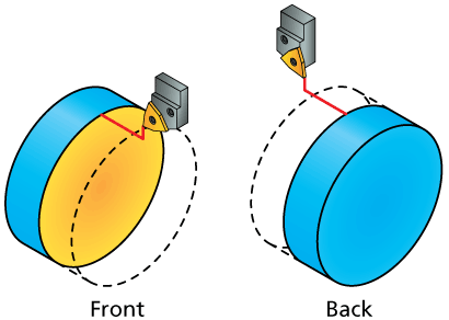
Mode
This section enables you to choose
the side of the machining. The Front
|
 |
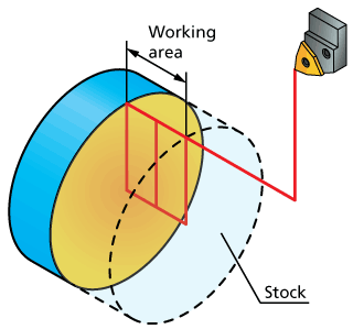
Working area
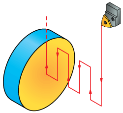
This section enables you to define where the face turning will be started.
When this option is chosen, machining starts at the stock boundary. The maximal (if Front is chosen for Mode) or minimal (if Back is chosen for Mode) Z-coordinate of the stock is automatically determined. The cutting passes parallel to the X-axis are distributed between this coordinate and the geometry. |
 |
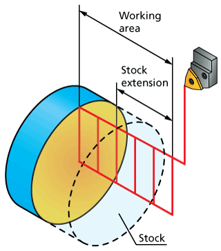
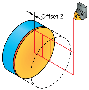
When this option is chosen, machining starts at the offset from the target defined in the corresponding edit box. |
 |
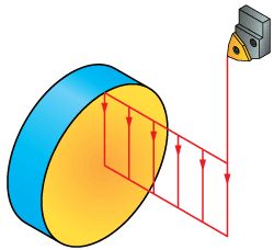
Direction
This section defines the direction of the tool movements.
The tool path passes are performed only in the direction of the geometry; the tool returns to the starting point of the next pass in the Rapid mode (G0) outside of the material. |
 |
The tool path passes are performed both in the direction of the geometry and in the reverse direction. After reaching the end of the first pass, the tool performs the next pass in the opposite direction, and so forth. |
 |
Rough


Offset
This section enables you to define the offset along the Z-axis that will remain unmachined during the roughing, i.e. the allowance for the further finishing.
More |
 |

This parameter is available only when the Rough section is activated.
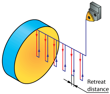
Retreat distance
This parameter enables you to define the distance to which the tool retracts after each cutting pass in case of One way machining. The retract movement is performed along the Z-axis over the cutting level. Then the tool moves parallel to the X-axis to the start point of the next cutting pass; the movement is performed in the Rapid mode. Then the tool descends along the Z-axis to the next cutting level and continues the machining. |
 |
This parameter is available only when One way is chosen for Direction.
Use cycle
This option enables you to define whether the turning cycles of the CNC-machine will be used (the check box is selected) or the tool path movements will be generated by SolidCAM (the check box is not selected).
When this check box is selected, SolidCAM updates the geometry according to the tool shape and generates the GCode for the CNC-controller cycle including the parameters required to execute the cycle and the GCode of the updated geometry.
In this case, the simulation might be slightly different from the actual machine cycle.
When this check box is not selected, SolidCAM updates the geometry according to the tool shape and then calculates the minimum tool movements required taking into account the material boundary in the beginning of the operation.
With rapid
When this check box is selected, the tool approaches the material at each Step over in the Rapid mode.
Finish
When this check box is selected, a single finishing pass is performed in the end of the operation.
Compensation
This option enables you to use the compensation of the tool nose radius.
When this check box is not selected, the radius of the tool nose is not taken into account when calculating the tool movements. No tool nose radius compensation (G41/G42) is used in the GCode.
When this check box is selected, the radius of the tool nose is not taken into account when calculating the tool movements. However, the tool nose radius compensation (G41/G42) is used in the GCode.
X output
The Negative X output option enables you to perform turning in the negative direction of the X-axis. The tool mounting and offset should be chosen accordingly.
The offset for the negative X output is applied to the absolute dimension on the X-axis.
Related Topics