External Contour tool
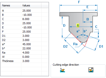
Definition
A |
The width of the tool holder. |
B |
The distance between the center of the radius of the tool tip and the left side of the tool holder. |
C |
The height of the tool tip. |
D |
The height of the tool (not including the turret). It must be greater than C. |
D1, D2 |
The lengths of the two cutting edges of the tool tip. These lengths define the maximum step down during turning. |
a° |
The tool tip right angle; must be between -90 and 90 degrees. |
b° |
The tool tip left angle; must be between -90 and 90 degrees. |
E |
The position of the left side of the turret with reference to the tool tip point. A negative value means that the turret will start before the tool tip point. |
F |
The width of the turret. |
Ra |
The tool nose radius. |
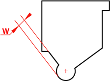
W |
The offset from the radial surface of the insert to the left side of the tool. |
Thickness |
The thickness of the tool. |
Round turning tool inserts support
SolidCAM enables you to define the geometry of the round turning tool inserts.
When the W value is entered, SolidCAM generates the tool with a round insert.
Related Topics