External Groove tool
Definition
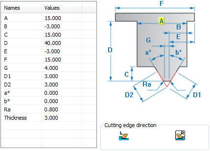
A |
The width of the tool holder. |
B |
The distance between the center of the radius of the tool tip and the left side of the tool holder. |
C |
The height of the tool tip. |
D |
The height of the tool (not including the turret); must be greater than C. |
D1, D2 |
The lengths of the two cutting edges of the tool tip. These lengths define the maximum step down during grooving. |
a° |
The tool tip right angle; must be between -90 and 90 degrees. |
b° |
The tool tip left angle; must be between -90 and 90 degrees. |
E |
The position of the left side of the turret with reference to the tool tip point. |
F |
The width of the turret. |
G |
The lower width of the tool tip. |
Ra |
The nose radius of the right side of the tool tip. |
Rb |
The nose radius of the left side of the tool tip. |
Thickness |
The thickness of the tool. |
Round turning tool inserts support
SolidCAM enables you to define the geometry of round turning tool inserts.
If the Ra value (nose radius of the right side of the tool) is greater than G/2 (half of the lower width of the tool tip) SolidCAM generates the tool nose as the round insert as shown below. The Rb field will be unavailable.
Related Topics