Geometry Edit dialog box
This dialog box enables you to define the geometry by selecting chains of wireframe elements.
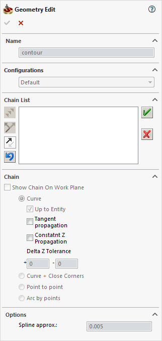
Name
This option enables you to define the name of the geometry. SolidCAM offers you the Default Geometry name that can be edited.
Configurations
This option enables you to switch between SOLIDWORKS configurations. Choose the necessary configuration for the geometry definition.
Adding a chain
You can add a chain to the existing set of chains in the current geometry. The new chain is added under the next sequential number.
1. Select the chain geometry using the Chain section options.
2. Confirm the chain definition with the ![]() button.
button.
Managing chains
All the selected chains are displayed in the Chain List section. To edit these chains, right-click on the chain name and choose the appropriate command from the menu.
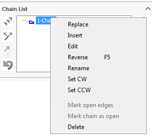
This command enables you to update a chain in the current chain geometry. The old chain is deleted and you can now define the new chain.
This command enables you to insert a chain between two existing chains.
This command enables you to edit an existing chain. You can reverse the chain or undo the selection steps to change the chain.
This command enables you to reverse the direction of the chain.
This command enables you to rename the geometry chain.
This command enables you to set the clockwise/counterclockwise direction to the chain.
This command deletes the chain from the current geometry.
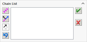
Chain buttons
When selecting entities to define a chain, the following buttons are available in the Chain List section:
|
To simplify the process of defining chains, you can also use the hot keys associated with the Add Selected Element, Change Direction, Reverse and Undo step options as described below. |
This option enables you to add the entity highlighted with the direction arrow to the current chain and continue the process according to the chosen criteria.

This option enables you to toggle between available chain entities following the current segment.
 Reverse (F8
hot key)
Reverse (F8
hot key)
This option enables you to reverse the direction of the chain you are currently working with. The direction is indicated by an arrow at the chain start point.
 Undo step (Backspace
hot key)
Undo step (Backspace
hot key)
This option enables you to undo the last selection of a chain element.
 Accept chain
This option enables you to confirm the single chain selection.
|
You can also use the Ctrl button on your keyboard to accept a chain and select the next one. To do it, instead of clicking Accept Chain, press the Ctrl button and hold it, while you are choosing a new chain. The first chain will be accepted. |
 Reject chain
This option enables you to cancel the single chain selection.
Chain direction
Operations in SolidCAM
use the direction of the chain geometry to calculate the tool
path. |
|
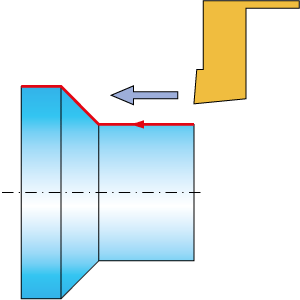
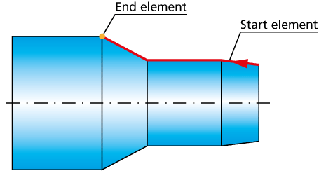
When you pick the first chain entity on the solid model, SolidCAM determines the start point of the picked entity closest to the picked position. The direction of the picked first chain entity is defined automatically from the start point to the picked position. |
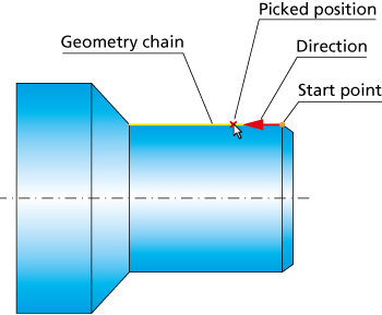 |
Use the ![]() button to reverse the direction of the
chain, if necessary.
button to reverse the direction of the
chain, if necessary.
Selecting entities
Show Chain on Work Plane
This option displays the projection of the selected chain on the working plane.
You can define the contour by selecting edges, sketch segments and points on the contour. SolidCAM provides the following options:
|
|
Associativity
SolidCAM will keep the associativity to any edge or sketch entity. Any change made to the model or sketch will automatically update the selected geometry.
|
The chain is selected by specifying the start curve, the direction of the chain and the element up to which the chain will be created. This command is useful if you want to define an open chain up to a certain point or edge. |
 |
Tangent propagationSolidCAM automatically selects the next entity tangent to the current one. If there is no any, it highlights all entities connected to the last chain entity. You have to select the entity along which you want the chain to continue. |
|
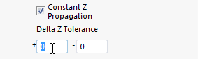
Constant Z PropagationThis option identifies only entities on the same XY-plane with the previously selected chain entity. You are only prompted to identify the next chain element when two entities on the same Z-level are connected to the chain. You are required to enter a positive and negative Z-deviation into the Delta Z Tolerance edit boxes. Only entities within this range are identified as the next possible entity of the chain.
|
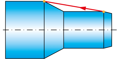
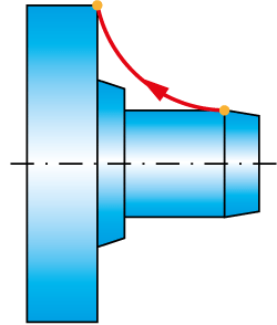
This option enables you to close the gaps between successive chain entities irrespective of the Gap Minimum and Gap Maximum values by virtually extending the entities up to their intersection.
Splines and arcs are extended by lines tangential to the arc/spline at its end point.
Pick start curve - select the first entity (a wireframe element or the solid model edge).
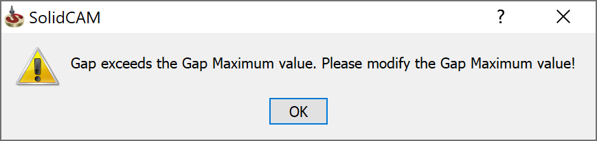
Pick next curve - select the next curve that belongs to the chain. When a gap is detected between these entities, the chain is continued by virtually extending the selected entities, according to the direction of the first entity, up to the virtual intersection point. If an intersection point cannot be found by extending either one or both selected entities, the following message is displayed:
|
In case several possible intersection points exist, the point closest to the last vertex of the first selected entity is chosen. |
To complete the selection, click
.
|
Associativity When the model used for the geometry definition is modified, SolidCAM enables you to synchronize the geometry with the updated model. During the synchronization SolidCAM determines gaps areas created using the Curve + Close Corners option and regenerates the extension of the chain elements so as to close the gaps. |
|
 |
Associativity SolidCAM will not keep the associativity to any selected point. SolidCAM saves the X, Y and Z coordinates of the selected points. Any change made to the model or sketch will not update the selected geometry.
|
 |
Associativity
SolidCAM will not keep the associativity to any selected arcs by points. SolidCAM saves the X, Y and Z coordinates of the selected points. Any change made to the model or sketch will not update the selected geometry.
Spline approximation
This section enables you to define the Spline approximation tolerance for the chain selection.
Related Topics