Preparing geometries
SolidCAM enables you to use SOLIDWORKS sketch entities and solid model edges as geometries for the Turning operations.
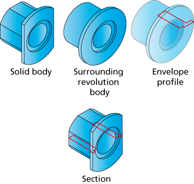
Envelope and Section
In the process of the Target model definition, SolidCAM creates a new sketch in the CAM component of the SolidCAM Part Assembly. This sketch contains either the envelope line of the specified solid bodies (Envelope sketch) or a section of the Target model by the ZX-plane (Section sketch).
Consider the revolution body surrounding the specified solid bodies. The section of this revolution body by the ZX-plane of the Turning Machine CoordSys is the envelope; this envelope is a profile of the part that has to be turned in order to create the model geometry. The Envelope sketch includes all the external model faces as well as the internal faces. The Envelope geometry can be used for the Geometry definition in SolidCAM operations. The Section sketch is a diametric section of the Target model by the ZX-plane.
In addition to automatically generated Envelope or Section geometry, SolidCAM enables you to prepare a geometry using SOLIDWORKS tools.
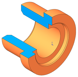
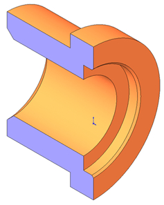
Creating Section
With this method, the Cut-Extrude feature has to be used in order to cut the model (half or quarter). The resulting Solid model contains edges that can be used for the geometry definition.
|
|
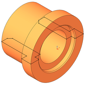
Creating Intersection curve
This command enables you to create an intersection curve between the Solid Model and section plane. The plane used for this operation has to traverse the revolution axis.
Open a new sketch on the section plane.
Choose the Tools > Sketch Tools > Intersection Curve commands.
Click the SOLIDWORKS Part icon in the FeatureManager Design tree.
The intersection curve will be created.
Close the sketch.
The resulting sketch entities can be used for the SolidCAM Geometry definition.