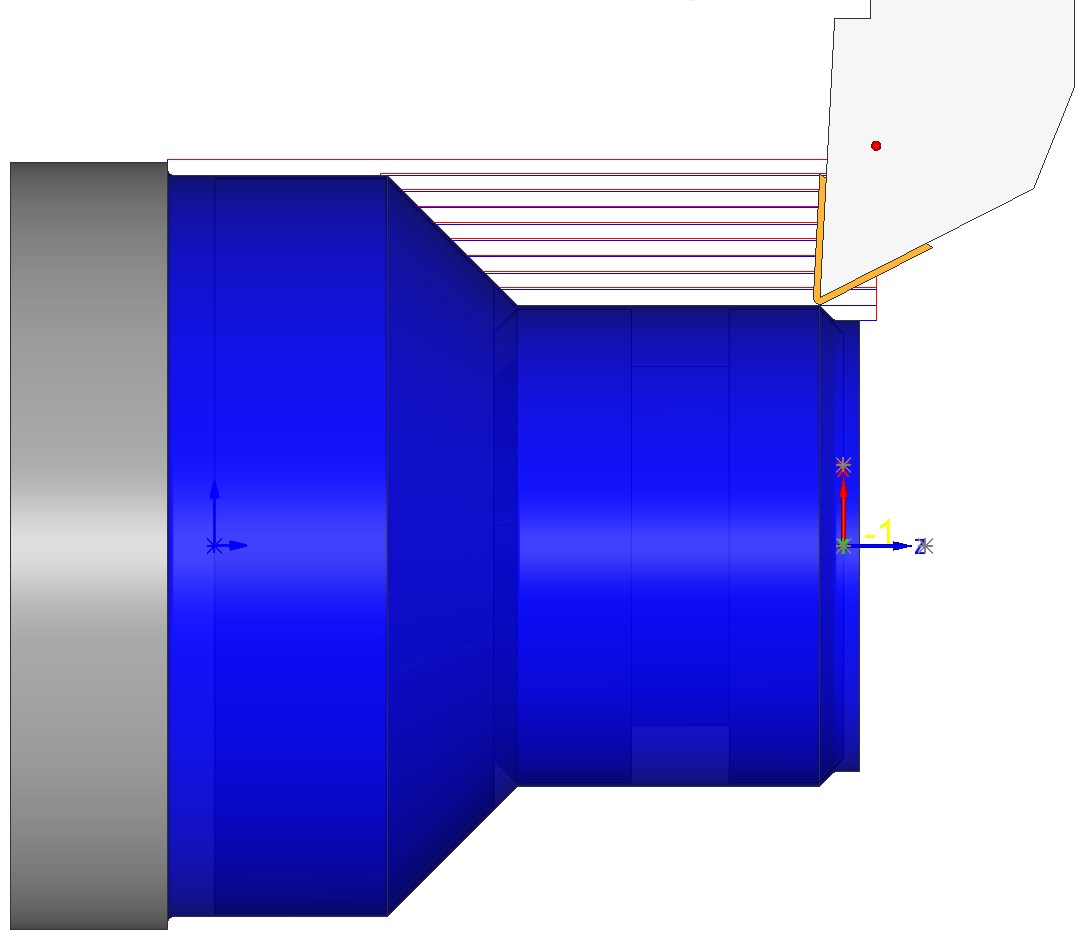
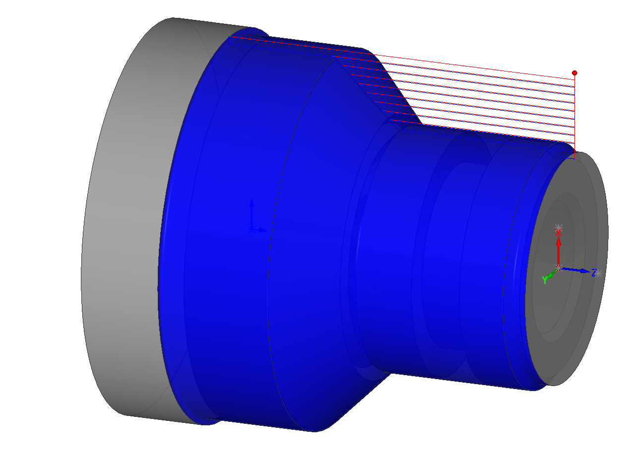
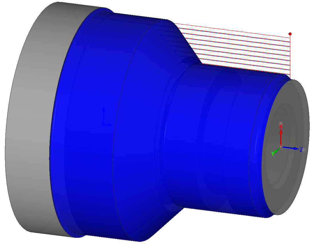
Host CAD simulation mode
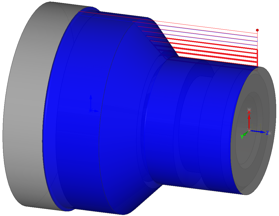
This simulation mode enables you to display the tool path directly on the model in the SOLIDWORKS window. Since all the View options of SOLIDWORKS are active during the simulation, you can see the tool path from different perspectives and zoom to various areas of the model.
|
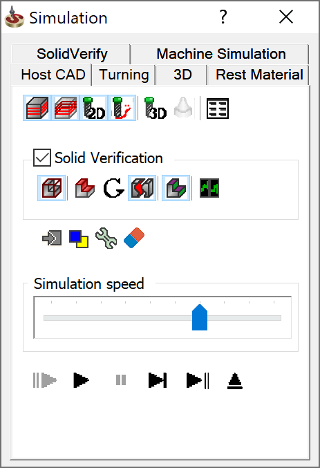 |
Simulation control panel
The Simulation control panel offers you the following controls to manage the simulation:
Show Tool path 
This option toggles on/off the tool path for the current operation.
Show Hidden lines 
This option toggles on/off the display of tool path lines hidden by the model geometry.
|
 |
|
|
Show tool 2D 
This option toggles on/off the graphic simulation of the tool.
Show
trail 
This option displays several previous elements of the tool path by highlighting them with a different color. The color is defined in the Simulation settings. |
 |
Show tool 3D 
This option toggles on/off the 3D graphic simulation of the tool.
Show holder 
This button toggles the display of the tool holder during simulation. The option is enabled only with Show tool 3D.
Solid Verification
These options enable you to display machining simulation on the solid model similar to SolidVerify using the SOLIDWORKS model.
Show
Stock 
This option displays how the stock is updated during the simulation.
Show
rest material 
This option uploads the target model and highlights the areas with left material. The highlighting color is defined in the Simulation settings.
Show
gouges ![]()
This option displays the gouge report.
Enable
automatic stock splitting 
This option toggles on/off the automatic splitting of the stock.
Colorize
stock 
This option enables you to display the updated model surfaces in the same color as the tool's color.
Multi-Core
support 
This option enables you to perform multicore calculation of the simulation. It means that the CPU performance of your computer is optimized in such a way that allows simultaneous calculation of different elements by different central processing units (cores). In this case, the animation is faster, but looks less accurate.
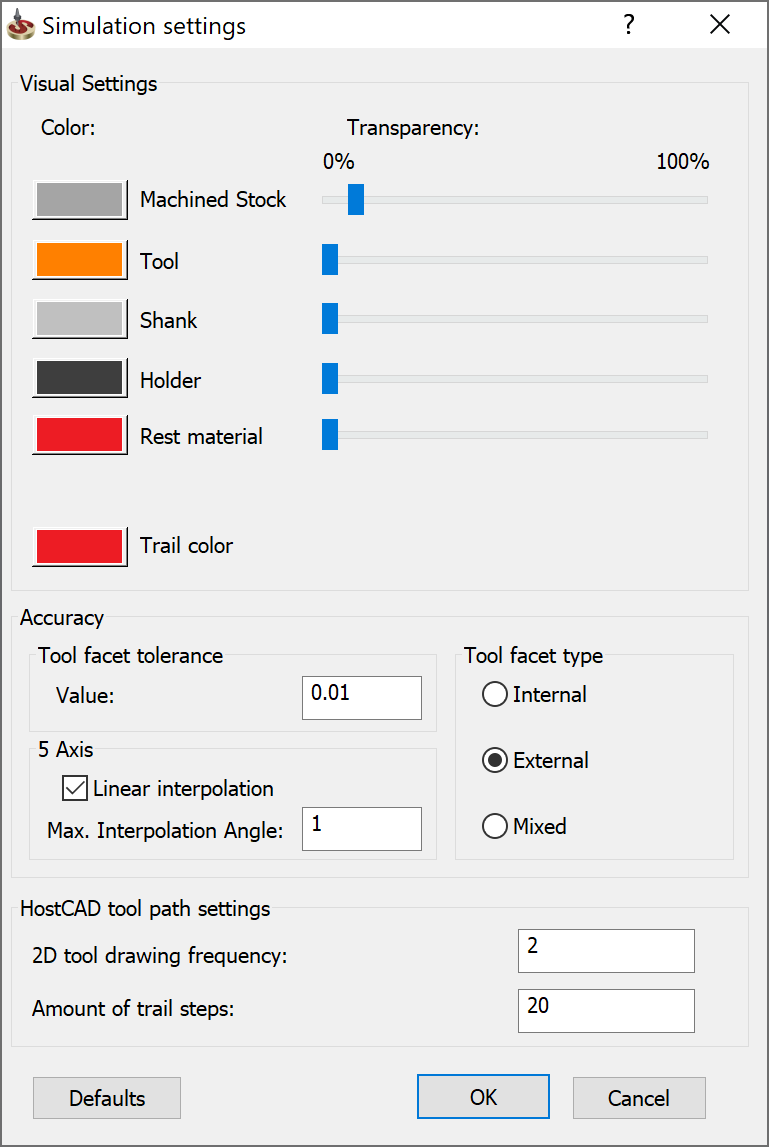
Settings
Clicking the Settings
This section enables you to define the color and transparency level for various model elements: Machined Stock, Tool, Shank, Holder, and Rest Material. You can also set the trail color. This section enables you to define the type and tolerance value of the tool facet used in Solid Verification. The 2D tool drawing frequency field defines the number of steps between showing the tool position. The Amount of trail steps value defines the number of tool path lines that are marked as trail. |
 |
Related Topics