Simulation control panel
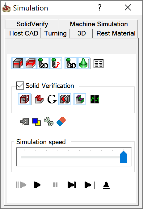
The Simulation control panel contains controls used to manage the simulation.
The following controls are common for all simulation modes:
Show data
Select this check box or click ![]() to display
the Simulation Data dialog box
that contains information about the tool path.
to display
the Simulation Data dialog box
that contains information about the tool path.
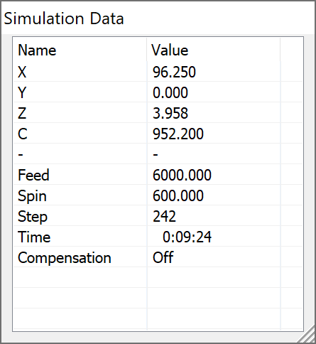
- The X, Y, Z fields display the position of the tool relative to the CoordSys at every step of the simulation.
- The Step field displays the number of steps of the simulation.
- The Feed field displays the current feed rate.
- The Time field shows the elapsed machining time of the simulated operations (theoretical value based on feed and distance covered).
Stop on Next
![]() This option displays the
Stop on Next dialog box where you can define the specific point
to stop the simulation process.
This option displays the
Stop on Next dialog box where you can define the specific point
to stop the simulation process.
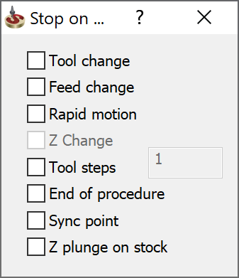
- Tool change - this option stops the simulation every time the tool changes.
- Feed change - this option stops the simulation every time the feed changes.
Rapid motion - this option stops the simulation every time when the rapid motion is performed.
Z Change - this option stops the simulation at every change of the Z-coordinate of the tool.
- Tool steps - this option stops the simulation every defined number of tool steps.
- End of procedure - this option stops the simulation at the end of the procedure.
- Sync point - this option stops the simulation of the balanced roughing, when one tool waits for another in a synchronization point.
- Z plunge on stock - this option pauses the simulation when tool plunges in the Z direction in rapid motion and comes in contact with the stock.
Colors
Click ![]() to change the display
color of the simulated tool path. The Simulation Colors dialog
box is displayed.
to change the display
color of the simulated tool path. The Simulation Colors dialog
box is displayed.
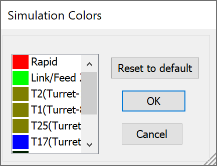
- To change the tool color, click the colored rectangle to the left from the tool number.
- The standard Windows color dialog box is displayed.
- Select the new tool path color for this tool number.
- Confirm with the OK.
|
Use the Reset to Default button to apply the default tool colors, as defined in the CAM Settings dialog box. |
Settings
Clicking the Settings
![]() to display the Simulation
Settings dialog box.
to display the Simulation
Settings dialog box.
Clear
![]() clears the simulated tool
path and the tool images from the graphic area.
clears the simulated tool
path and the tool images from the graphic area.
Simulation speed
The slider controls the simulation speed. The speed set in a current operation is saved for a next operation simulation.
Simulation controls
The control buttons enable you to run and stop the simulation:
")
Turbo mode- The simulation is performed in the computer memory without showing on the screen. The image is shown when the simulation is completed or when you click on the Pause button. Play- Use this button to play the simulation in continuous mode. Loop mode- automatically repeats the simulation from the beginning. This mode is activated by pressing and holding the Play button for two seconds. Press and hold again the Loop button to switch back to the Play mode.
Pause- Use this button to pause the simulation played in continuous mode. Single Step mode- Use this button (or the space bar of your keyboard) to simulate the tool movements step-by-step. Operation step mode- The simulation is displayed operation by operation. Exit- Use this button to exit from the simulation module.

Related Topics