SolidCAM Manager
Introduction
The SolidCAM Manager is the main interface feature of SolidCAM. It displays complete information about the CAM-Part.
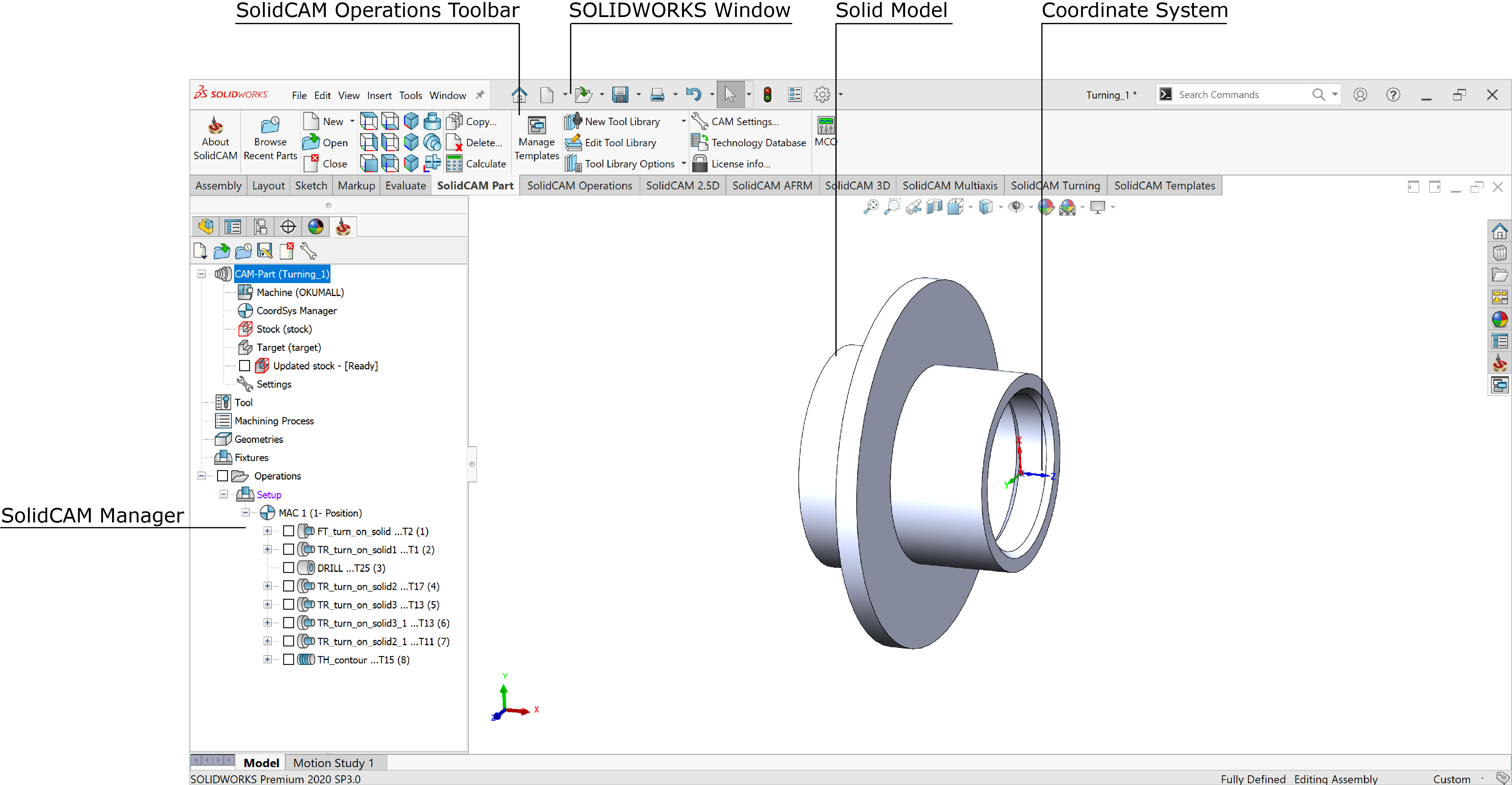
The SolidCAM Manager contains the following headers:
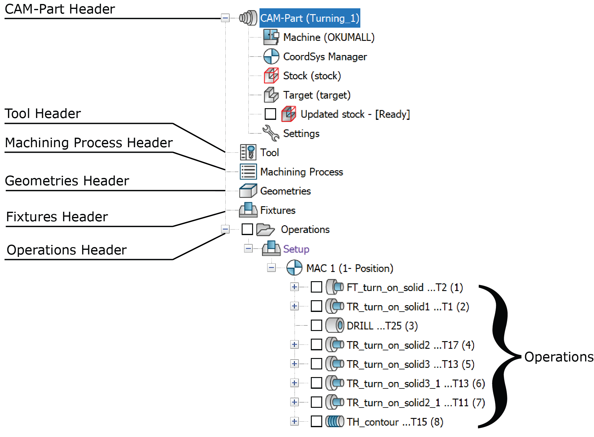
This header displays the name of the current SolidCAM CAM-Part. By right-clicking it, you can activate the CAM-Part menu to manage your CAM-Parts. The Machine, CoordSys Manager, Stock, Target, Updated stock and Settings subheaders are located under the CAM-Part header. Double-clicking the CAM-Part header displays the Turning Part Data dialog box.
This header displays the name of the current Tool Table. By right-clicking it, or Double-clicking on the Tool header displays the Part Tool Table.
This header displays the name of the current Machining Process Table. By right-clicking it, you can activate the menu to manage the MP Tables. Double-clicking the Machining Process header displays the Current Machining Processes Table Manager.
This header displays all the SolidCAM geometries that are not used in the operations. You can get the list of these geometries by clicking on the "+" icon near the Geometries header. You can display the geometries managing menu by right-clicking the Geometries header. You can also open the relevant menu by right-clicking each geometry name. Double-clicking a geometry name displays the selected geometry.
This header displays all the fixtures that are not used in the operations. You can get the list of these fixtures by clicking on the "+" icon near the Fixtures header. You can display the fixtures managing menu by right-clicking the Fixtures header. You can also open the relevant menu by right-clicking each fixture name. Double-clicking a fixture name displays the selected fixture.
Operations header
This header shows you all the SolidCAM Operations. The operations managing menu is available by right-clicking the Operations header. You can get the relevant menu also by right-clicking each operation name.
Double-clicking an operation name enables you to edit operation parameters with the specific operation dialog box. If you double-click an operation name when another operation dialog box is open, the last dialog box will be closed.
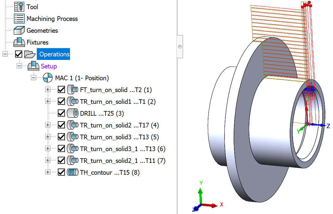
The check box near the Operations header enables you to display the tool path for all the CAM-Part operations directly on the SOLIDWORKS model from the CAM Manager.
The check box near the CAM Operations enables you to display the tool path directly on the SOLIDWORKS model.
- Highlight Tool path - When the process of calculating an operation is completed, the check box before the operation is automatically selected and the tool path is displayed on the SOLIDWORKS model. To highlight a particular tool path, select the Operation from the Operations Header. The tool path for that particular operation is displayed in bold on the SOLIDWORKS model.
 |
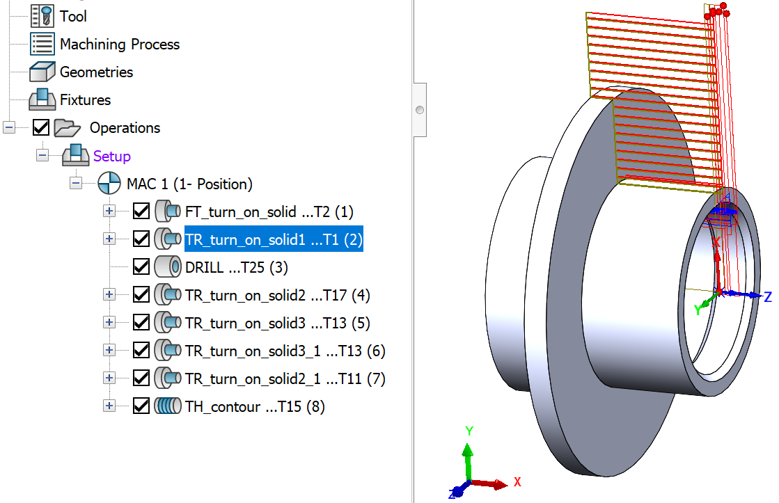 |
Operation Not Selected |
Operation Selected |
Special symbols
CAM-tree entities can use special symbols and conventions.