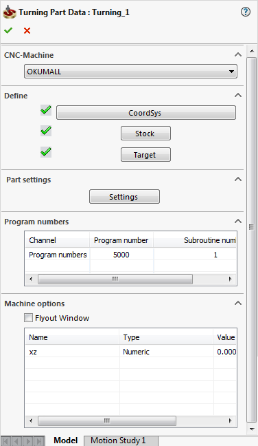
Turning Part Data dialog box
In the Turning Part Data dialog box, you specify all the information relevant to the machining project or workpiece you want to manufacture. The parameters and values defined at the CAM-Part level will later serve as default values for machining levels, etc. Naturally, all parameters can be changed in the particular machining operations. The check mark next to the CoordSys (Coordinate System), Stock and Target indicate that these parameters have already been defined.
If a parameter has not yet been defined, the corresponding space is empty. |
 |
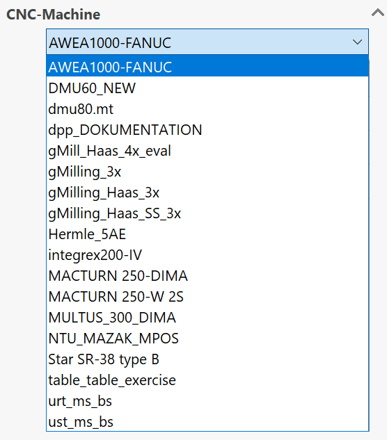
CNC-Machine
This field enables you to choose the CNC-Machine controller. Click the menu to display the list of post-processors installed on your system and choose the machine you want to use.
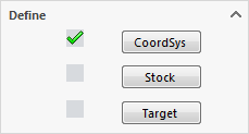
Define
SolidCAM enables you to define the Coordinate System directly on the solid model by clicking CoordSys.
The Coordinate System is the origin of the CNC-Machine coordinate system through which the symmetry line for the turning passes; when the CAM-Part is prepared on the machine, you must make sure that the CoordSys of the machine is the same as the CoordSys chosen in SolidCAM. You should define the CoordSys before you continue with the definition of the other fields in this dialog box.
Clicking Stock, you can define the boundaries of the Stock material used for the CAM-Part.
Clicking Target, you can define the Target model - the final shape of the CAM-Part after the machining.
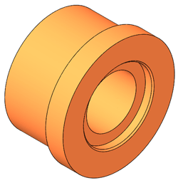
SolidCAM will use the Target model for the gouge checking in the SolidVerify simulation.
Part Settings
Settings enables you to define a number of parameters specific for the current CAM-Part.
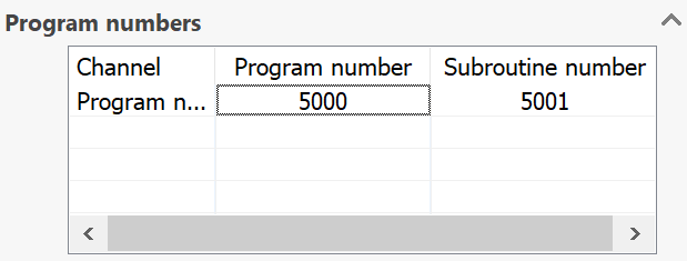
Program numbers
Using the Program numbers table, you can define the Default GCode numbers of the current CAM-Part.
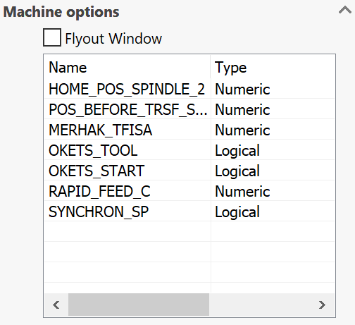
Machine options
If the Machine ID file of your CNC-Machine has extra parameters defined, they can be accessed in this section.
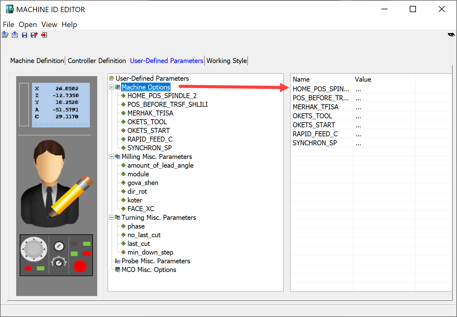
In the Machine options table, you can add unique information related to the machine controller you have selected. If you prefer working with a larger table, the Flyout option displays the Machine Options List window.
When you confirm the Turning Part Data dialog box, SolidCAM generates a *.prt file and a subfolder that contains all information, models and GCode files of the CAM-Part. The CAM-Part is stored in your current user directory.