CAM-tree Legend
CAM-tree entities use the following conventions and symbols:
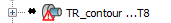
| The synchronization mark displayed next to the geometry icon means that a misfit is determined between the SOLIDWORKS model and the SolidCAM geometry. It can also appear if there is a gap or overlapping entities. To resolve the issue, perform the Synchronization check. | |
 |
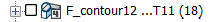
The exclamation mark means that the geometry cannot be updated. You have to edit this geometry and manually update problematic chains. |
| The grayed out name of the operation means that the operation is suppressed. | |
| The black rectangle around the operation name means that the GCode of the operation is suppressed. | |
| The lock symbol displayed on the operation icon means that the operation is locked during the parallel calculation. | |
| The red square displayed on the operation icon means that the operation contains an error, for example, the submachine has an empty table (no stock has been loaded). Hover the mouse pointer over the operation to get an exact explanation. | |
 |
The cyan circle displayed on the operation icon means that the Milling operation calculates and updates the material boundary to be used in following turning operations. |
| The green diamond symbol instead of the tool path check box before the operation icon means that the operation is modified with the Tool Path Editor. | |
| The asterisk symbol instead of the tool path check box before the operation icon means that the operation is not calculated. | |
| The red color of the font means that the operation is incomplete. |
You can use the tool path display check box to toggle between showing and hiding the tool path.