Geometry
This page enables you to define the geometry for the Geodesic Machining operation.
Geometry surfaces
Geometry selection
In the Geometry selection area, select Model or Surfaces. The Geometry surfaces are either the entire model or any surface(s) of the design model.
Machining surfaces
The Machining surfaces are the entire model or any surface(s) of the design model. If you have already defined 3D Model geometries for this CAM-Part, you can select a geometry from the list.
New
![]() enables you to define a new 3D
Model geometry for the operation with the 3D Geometry dialog box.
enables you to define a new 3D
Model geometry for the operation with the 3D Geometry dialog box.
Edit
![]() enables you to edit an existing
geometry.
enables you to edit an existing
geometry.
Browse
![]() enables you to view
the available geometries on the model and choose the relevant one from
the list.
enables you to view
the available geometries on the model and choose the relevant one from
the list.
Show displays the chosen 3D model geometry in the SOLIDWORKS window.
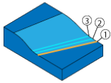
Drive surface offset
The Drive surface offset parameter enables you to define a machining allowance for the drive surface. The machining is performed at the specified distance from the drive surface.
Click Advanced to view the Advanced options for drive surface window.
Surface Normal
You can use this option to change the machining side. Machine on opposite side option generates tool path on the surface opposite to the surface direction.
|
|
Machine on opposite side not selected |
Machine on opposite side selected |
Rolling avoidance
| Fill holes- This option creates a mesh for all the holes simultaneously. The holes which should be filled are not chosen. Each boundary (except for the outer boundary of mesh) is considered a boundary of the hole. |
|
| No cuts in holes- This option is enabled when the Fill holes check box is selected. We can add boundaries of filled holes to containment curves. The hole boundary will be excluded from the curves used to generate the tool path. Incase, a containment curve around a hole has been defined, an exception will pop up. When this option is selected ensure that all input containment curves do not touch the boundaries of holes. |
|
| Extend mesh boundary option allows short curves to be extended to the surface boundary. The default value is 200. The value of Extend mesh boundary must always be positive. |
|
|
The Rolling Avoidance section is available only when Surfaces is selected in the Geometry Selection. |
Geometry curves
Pattern type
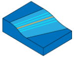
Pattern type defines how the tool path is generated with respect to the input curves. Two options are available.
|
When Morph between two curves is chosen, the options of First drive curve and Second drive curve are enabled and you must ensure that two curves are selected. |
Input type
Defines how to extract/define the curves for Pattern type.
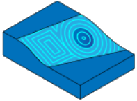
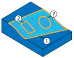
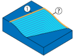
| Automatic (Machining area) extracts curves automatically from the defined Machining area. It can define the machining area only if the surface has a boundary. |
|
||
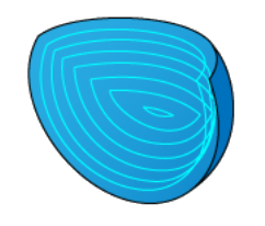
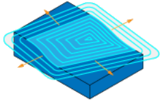
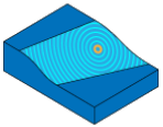
| Automatic (center point) generates parallel curves that are morphed between center point and the surface boundary. The drive curve is defined as a closed curve which is positioned in the center of the machining surface. |
|
||
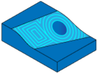
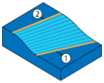
| User-defined curves allows you to manually define the curves to create passes from. When this option is selected the Drive curve section gets enabled. |
|
||
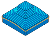
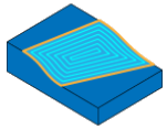
Automatic
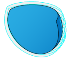
(Surface boundary) extracts the curves from the surface
boundary. It can define the surface boundary only if the
surface has a boundary.
|
|
This section enables you to morph the Constant Stepover pattern between multiple drive curves.
New
![]() allows you to select new drive curves.
allows you to select new drive curves.
Edit
![]() allows you to edit the selected
curve.
allows you to edit the selected
curve.
Show displays the selected curve.
Browse
![]() enables you to visualize the geometries
during the selection process. Clicking
enables you to visualize the geometries
during the selection process. Clicking ![]() displays the Browse Geometries
dialog box that lists all the geometries of the type suitable for the
chosen operation.
displays the Browse Geometries
dialog box that lists all the geometries of the type suitable for the
chosen operation.
Click Advanced to view the Advanced options for Guide curves window.
Area
The Area section enables you to define the cutting area on the drive surface.
Type
The Type list enables you to choose the following options:
| Entire machining area- This option is set by default to machine the entire area. By setting this option the tool path is generated on the whole surface and start and ends at exact surface edge. |
|
| Determined number of cuts- This option allows you to set the defined Number of cuts to machine the area. The default value is set to 5. The value entered in this field must be positive or equal to zero. |
|
Step direction
Step direction defines the tool path generation direction relative to the curves. This feature determines which side of the machining is used as the step direction. This section is enabled when Parallel to multiple curves is selected in the Pattern type section.
| Side One - The inner portion of the guide curve is machined. Side one is set as default. | 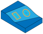 |
| Side two -The outer portion of the guide curve is machined. | 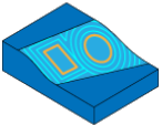 |
Start type
| Shift to guide lets the first pass to shift from the selected guide. This option adds an extra margin at each guide curve or morph curve. The extra margin is half the given stepover. | 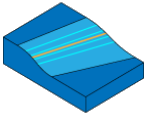 |
| Start on guide lets the first pass to generate on the selected guide. The option keeps the cuts on the drive curve. |  |