Tilt tool
The Tilt tool option enables you to avoid the possible collisions by the tool tilting.
SolidCAM enables you to choose from different options to define the direction of the tool tilting.
Use lead/lag angle
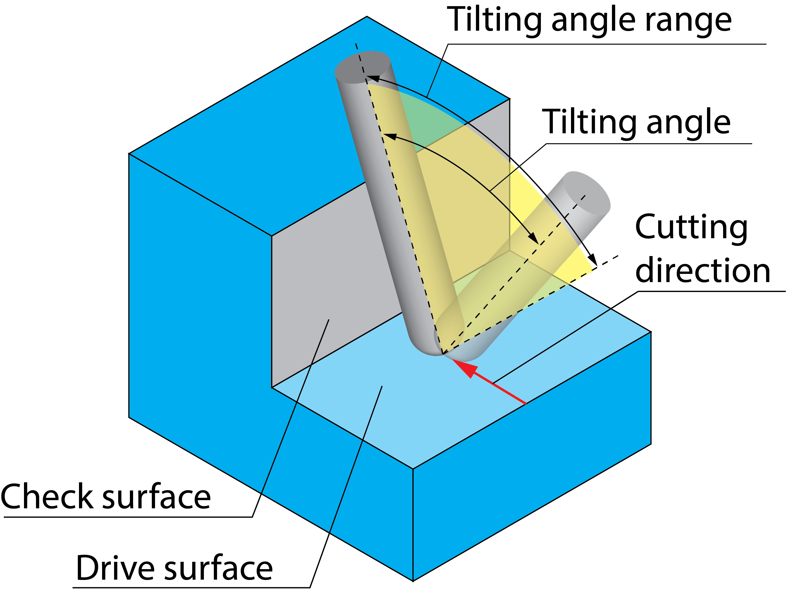
With this option, the tool tilting is performed in the cutting direction.
Advanced enables you to choose the tilting direction and specify the range for the tilting angle in the Angles to avoid collisions dialog box.
When the positive direction (+) is chosen for Maximum tilt angle, the tool can tilt in the positive cutting direction at an automatically chosen angle. The angle is within the range from 0 to the specified value. When the negative direction (-) is chosen, the tool tilting is performed in the negative cutting direction. When plus-minus direction (±) is chosen, SolidCAM automatically chooses either positive or negative direction of the tilting and performs it at an angle from the specified range.
The Clearance angle protects the tool tip flat end back side against collisions with the drive face. |
|
In this illustration, possible collision is detected and avoided by tool tilting. The tool tilting is performed in the negative cutting direction. The tilting angle is chosen automatically from the specified range. |
 |
Smoothing enables you to smooth the tool path in its cutting direction, as well as the side tilt angle in the Side tilt angle dialog box.
The smoothing is defined according to a rotary axis and can be applied in multiple ways.
- To the tilt angles away and towards the specified axis. You have to define minimum and maximum angles that provide the range of freedom of the smoothing which should be used to smooth out the tool axis orientations away and towards the rotary axis.
- To the angles which tilt around that axis. You have to define minimum and maximum angles that provide the range of freedom of the smoothing which should be used to smooth out the tool axis orientations around the rotary axis.
First, select an appropriate rotary axis. The minimum and maximum values of the tilt and rotary angles depend on how much freedom you would like to allow.
The Use blend section enables you to define the Distance between the collision point and the point where the tool tilting starts.
Use side tilt angle
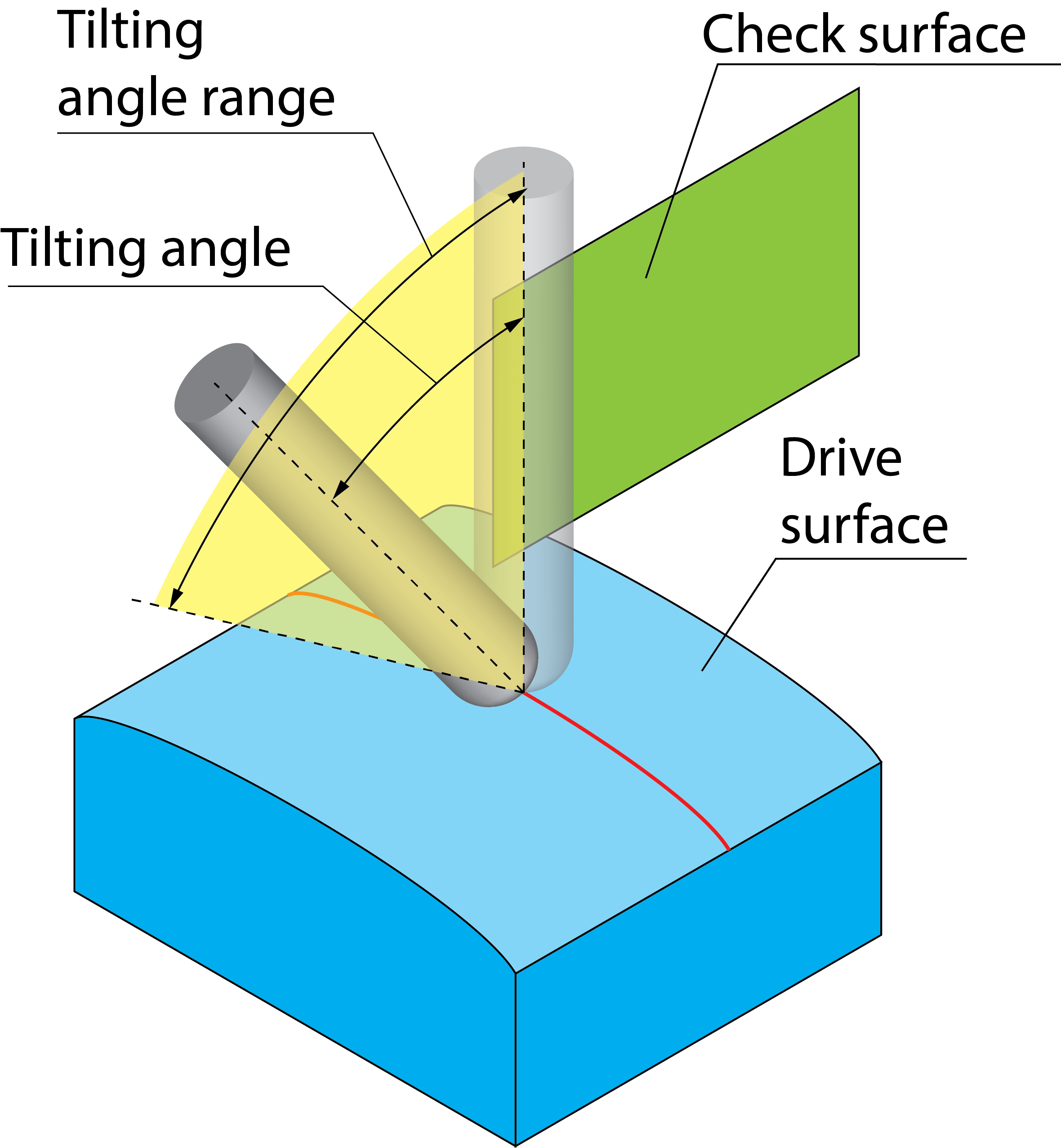
With this option, the tool tilting is performed in the side direction, relative to the cutting direction.
The Advanced button enables you to choose the tilting direction and specify the range for the tilting angle in the Angles to avoid collisions dialog box.
When the positive direction (+) is chosen for Maximum tilt angle, the tool tilting is performed at an automatically chosen angle to the right side relative to the cutting direction. The angle is located in a range from 0 to the specified value. When the negative direction (-) is chosen, the tool tilting is performed to the left side relative to the cutting direction. When plus-minus direction (±) is defined, SolidCAM automatically chooses the direction of the side tilting and performs it at an angle from the specified range. Minimum tilt enables you to define the minimum tilt angle.
The Clearance angle protects the tool tip flat end back side against collisions with the drive face. In this illustration, the possible collision of the tool with the check surface is detected and avoided by the side tilting. The tool tilting is performed to the left side relative to the cutting direction. The tilting angle is chosen automatically from the specified range. |
 |
The Smoothing button enables you to smooth the tool path in its cutting direction, as well as the side tilt angle in the Side tilt angle dialog box.
The smoothing is defined according to a rotary axis and can be applied to the following:
- To the tilt angles away and towards the specified axis. You have to define minimum and maximum angles that provide the range of freedom of the smoothing which should be used to smooth out the tool axis orientations away and towards the rotary axis.
- To the angles which tilt around that axis. You have to define minimum and maximum angles that provide the range of freedom of the smoothing which should be used to smooth out the tool axis orientations around the rotary axis.
First, select an appropriate rotary axis. Then define the minimum and maximum values of the tilt and rotary angles that depend on how much freedom you would like to allow.
The Use blend section enables you to define the Distance between the collision point and the point where the tool tilting starts.
|
The Smoothing button is not available when the option of Automatic is chosen from the drop down list. |
Automatic
With this option SolidCAM enables you to avoid possible collisions by performing the tool tilting automatically.
Tool path with Automatic not selected
|
Tool path with Automatic selected
|
|
|
Advanced displays the Advanced options for automatic tilting dialog box, which enables you to define the parameters used for the automatic tool tilting.
Tilting
The tool can be automatically tilted Relative to cutting direction or Relative to rotary axis.
Relative to cutting direction
When selected, the Lead tilt angle and Side tilt angle parameters are used for the automatic tool tilting.
Preference
Using the following options, you can prioritize the main approach for tilting the tool in order to prevent collisions:
Equal tilting – tilting is preferred equally in both the cutting and side directions.
Lead/Lag tilt – tilting is highly preferred in the cutting direction.
Side tilt – tilting is highly preferred in the side direction, relative to the cutting direction.
Relative to rotary axis
When selected, the Tilt angle and Rotary tilt parameters are used for the automatic tool tilting.
Rotary axis
From the list, you first have to define the rotary axis you want to use when avoiding collisions. SolidCAM enables you to use one of the Coordinate System axes (X, Y or Z), a line or the smoothing definition.
The Line
option displays the ![]() button, which by clicking enables
you to pick the start and end points of the rotary axis line directly
on the solid model.
button, which by clicking enables
you to pick the start and end points of the rotary axis line directly
on the solid model.
The Use smoothing definition option enables you to use the parameters defined for Smoothing in the Side tilt angle dialog box.
Preference
Using the following options, you can prioritize the main approach for tilting the tool in order to prevent collisions:
Equal tilting – tilting is preferred equally around and away from/towards the rotary axis.
Rotary tilt – tilting is highly preferred around the rotary axis.
Tilt – tilting is highly preferred away from/towards the rotary axis.
|
The options of Use lead/lag angle and Use side tilt angle are available only when the Tool axis direction is selected as Tilted relative to cutting direction or Tilted relative to impeller machining layer on Tool axis control page. |
Change fixed tilt angle
When Tilted to axis by fixed angle, Tilted through point, Tilted through curve, Tilted from point away, Tilted from curve away, is selected on Tool axis control page, and Change fixed tilt line is selected as Gouge check strategy, you can change the fixed tilt angle by adding or decreasing multiple values up to the maximum tilt angle value to avoid collisions.
Rotate around Z-axis
When Rotated around axis is selected on Tool axis control page, and Rotate around Z-axis is selected as Gouge check strategy, you can provide one tilting angle around the Z axis by adding or decreasing multiple values up to the maximum tilt angle value to avoid collisions.