Defining a Drilling geometry
In Drilling operations, you have to define the coordinate points where SolidCAM will execute the drilling cycles. The powerful selection tool enables you to define and edit drilling positions quickly and easily.
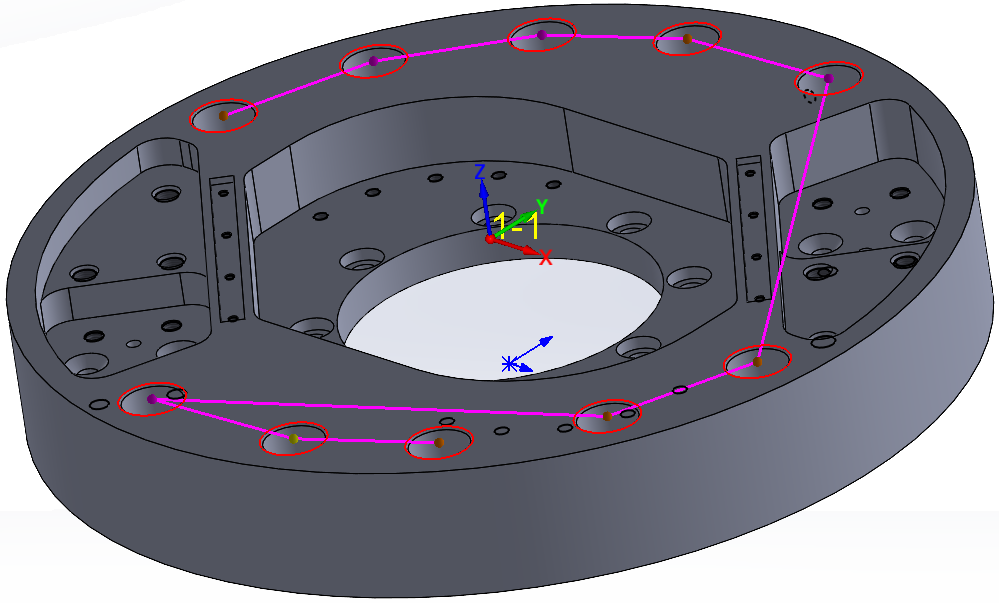
In this example, the drilling points have been selected by their radius and Z-level on a 3D solid model. With automatic selection the distance between two drilling points is optimized to reduce machining time.
![]() in the Geometry page of the Drilling
Operation and Thread Milling Operation dialog boxes enables you to choose
the mode of the geometry definition.
in the Geometry page of the Drilling
Operation and Thread Milling Operation dialog boxes enables you to choose
the mode of the geometry definition.
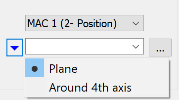
The Plane mode enables you to define the geometry on the plane/face parallel to the XY-plane of the current CoordSys. Click
 to display
the Drill
Geometry selection dialog box.
to display
the Drill
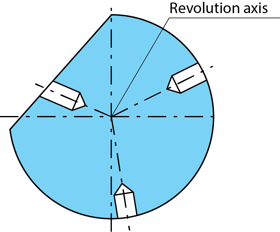
Geometry selection dialog box.The Around 4th axis mode enables you to select the drilling geometry wrapped on the solid model around the 4th axis. Clicking New displays the Around 4th Axis Drill Geometry Selection dialog box.
|
This method enables you to select only the holes whose axis intersects with the revolution axis of the CAM-Part.
This method can be chosen when the appropriate CoordSys that enables the use of the 4th axis is selected.
|
Related Topics