Drill Geometry Selection dialog box
For Drilling operations, you have to define the coordinate points where SolidCAM executes the drilling cycles.
The powerful selection tool enables you to define and edit drilling positions quickly and easily. Whenever you have to define a drilling geometry, the Drill Geometry Selection dialog box is displayed.

Name
This field enables you to define the name of the geometry. SolidCAM offers you the Default Geometry name that can be edited.
Configurations
This option enables you to switch between SOLIDWORKS configurations. Choose the necessary configuration for the geometry definition.
Select/Unselect drilling centers
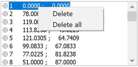
Use the Select/Unselect mode to add and remove drilling positions from the geometry. The Undo/Redo button cancels or restores the last selection. All the selected points are shown in the list at the bottom of the dialog box. To remove a point from the list, right-click its entry in the list and choose the Delete option from the menu or choose the Delete All option to remove all of the points.
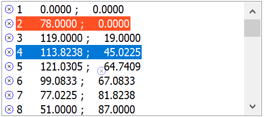
Sorting of drilling positions
You can change the sequence of drilling positions in the list by dragging and dropping.
|
You can also define and edit the sorting of drilling positions in the Drilling Operation dialog box. |
Selection modes (Select centers by)
You can add drilling positions to the current geometry using the following options:
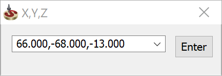
You can define drilling positions one by one using the CAD point selection options. You can also type the coordinates into the X,Y,Z dialog box and confirm each drilling point by clicking Enter.
- Pick drilling center position - select the drilling point.
- Confirm the selection by clicking Enter.
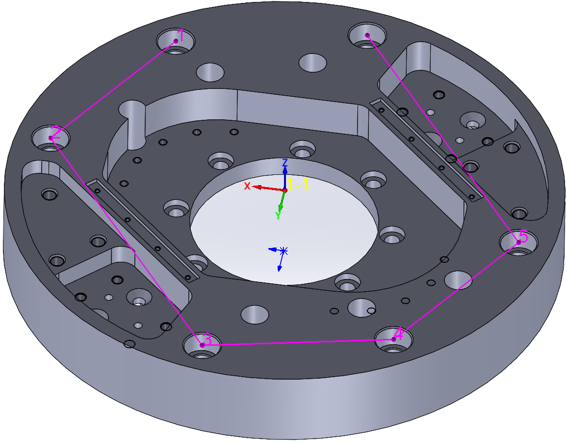
Usually, all curves and arcs of imported models are converted into splines by the exporting CAD system. Due to the nature of spline curves or surface boundaries, you cannot pick a center position like you could on a circle or arc. SolidCAM calculates the center position of an arc defined by three points positioned on the spline edges. This facilitates the selection of drilling centers on spline surfaces.
Pick the first point – pick a point on the circumference of the circle or arc using the CAD point selection options or type the coordinates into the X,Y,Z dialog box and confirm.
Pick the second point.
Pick the third point.
SolidCAM calculates the center of the three points and displays the drilling position.
With this option, you can select model faces. SolidCAM automatically determines all arcs/circles located on the selected face and defines the center points as drilling positions. You can also use the mouse to drag a box over the area of the model. SolidCAM automatically recognizes all arcs inside this area and defines the center points as drilling positions.
|
The options you have selected in Filter affect the search when you apply the Multi-positions command. |
Check whether the Filter options you have selected are correct.
Click on the solid model face.
SolidCAM starts searching the selected face for drilling positions and displays the search result.
|
Synchronization with Multi-positions When you add or delete holes on a face created using Multi-positions, during Synchronization check, SolidCAM compares the SolidCAM geometry and the SOLIDWORKS model. SolidCAM recognises the changes and automatically updates the geometry and re-calculates the operation. For automatic Synchronization, in the Synchronization page of Part Settings enable Synchronize automatically, Calculate operations after the synchronization and Associate the geometry with the current configuration.
|
Smart Face
The option of Smart face is unchecked by default. When any of the option of Filter for circle/arc selection is used, Smart face remains unchecked and is disabled.
When Smart face is checked, you can pick the face and synchronization works on that entire face. However, if a Filter is used selecting Smart face, Smart face option automatically unchecks and disables.
If Smart face is used and you want to delete a hole that was picked using Smart face, the following message is displayed:

Click Yes, the following message pops up

The moment you delete hole(s), Smart face is again disabled. You can enable Smart face again after all the holes are deleted.
SolidCAM searches the solid model for arcs and circles and adds all center points as drilling positions to the geometry.
|
The options you have selected in Filter affect the search result when using the All circle/arc centers command. |
SolidCAM enables you select the drilling geometry with the SOLIDWORKS selection tools.
- Check whether the Filter options you have selected are correct.
- Click CAD selection. The CAD selection changes to Resume.
- Select the geometry with SOLIDWORKS tools.
- Click Resume.
Selection filter (Filter for circle/arc selection)
You can use various filters to search circles/arcs on the model for drilling positions. SolidCAM selects only the drilling positions with the attributes set in the Filter options. You can select the following attributes:
If this check box is selected, SolidCAM also includes arc centers in the search for drilling positions. This option can solve the occasional problem caused by imported CAD models that have circle entities cut to halves. It also enables you to place drills in filleted corners.
- Include points
If this check box is selected, SolidCAM also includes sketch points in the search for drilling positions.
SolidCAM searches the entire model for circles. Arcs or broken circles are not included in the search result.
You can limit the search by defining a radius value. Only arcs and circles with the given radius are selected and their center position is added to the drilling geometry.
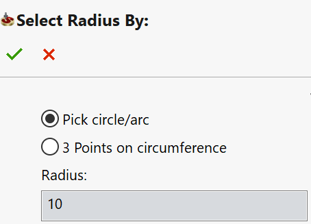
You can define the radius value on the model. Click By Radius. In the Select radius by dialog box you can choose how you want to pick the radius from your model. Select the corresponding option and pick the radius from an existing circle/arc or use the 3 Points on circumference definition.
You can also limit the search to the Z-level. Only arcs and circles on the given XY-plane are selected and their center positions are added to the drilling geometry.
You can select the Z-level on your model. Click On Z-level and select a point on your model using the point selection options. The Z-coordinate of the selected point is passed to the corresponding field.
Selected circles/arcs
When defining positions for the current drilling geometry, the following useful options are available:
- No longer can be selected – disables the selection of drilling positions already defined for the CAM-Part.
- Show the center points – shows the center positions selected in all drilling geometries of the CAM-Part.
Related Topics