HR Drill Geometry Selection dialog box
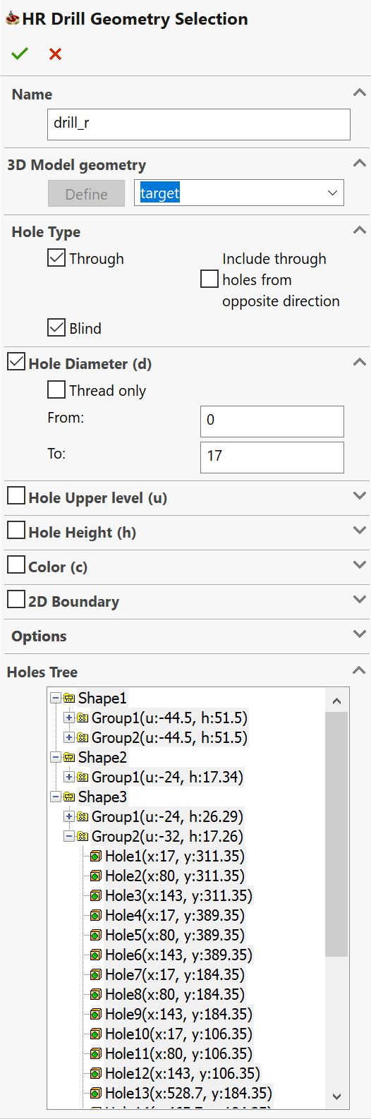
This dialog box enables you to define the geometry and manage the parameters of the drill recognition.
Name
This option enables you to define the name of the geometry. SolidCAM offers you the Default Geometry name that can be edited.
3D Model geometry
If you have already defined 3D Model geometries for this CAM-Part, you can select a geometry from the list.
Hole type
This section sets the recognition filter of hole features according to their type.
The Through check box enables you to recognize the through hole features.
The Blind check box enables you to recognize the blind hole features.
The Include through holes from opposite direction check box enables you to recognize all the through holes that are in the opposite direction (example Counterbore holes from opposite directions). If the Through check box is disabled the option of Include through holes from opposite direction will also be disabled.
|
When none of these check boxes is selected, hole recognition cannot be performed, and the Find Holes button is disabled. |
Hole diameter (d)
When this section is activated, the hole features are filtered according to the diameter of the hole. With this filter, only the hole features with the Hole diameter value within the specified range are recognized.
The From and To values enable you to define the Diameter range by entering the values or by picking on the solid model. When the cursor is placed in the From/To edit box, you can specify the diameter value by picking a specific cylindrical surface or a circular edge on the solid model. When a cylindrical surface or a circular edge is picked, its diameter is calculated and inserted into the corresponding edit box replacing the previous value. The edit box becomes pink. When you remove the automatically determined value, the edit box becomes white.
The Thread only check box enables you to recognize only the hole features with threads. The thread recognition is performed according to the SolidCAM Settings. When this check box is selected, the From and To values define the range of the Thread diameter values. The From and To values can be defined by picking a cylindrical surface, cosmetic thread or circular edge on the solid model.
Hole Upper level (u)
When this section is activated, the hole features are filtered according to the Upper level. With this filter, only the hole features with the Upper level value within the specified range are recognized.
The From and To values enable you to define the Upper level range by entering the values or by picking on the solid model. When the cursor is placed in the From/To edit box, you can specify the Upper level value by picking on the solid model. When a model point is picked, the Z-value of the picked position is calculated and inserted into the corresponding edit box replacing the previous value. The edit box becomes pink. When you remove the automatically determined value, the edit box becomes white.
Hole height (h)
When this section is activated, the hole features are filtered according to the Hole height. With this filter, only the hole features with the Hole height value within the specified range are recognized.
The From and To values enable you to define the Hole height range by entering the values or by picking on the solid model. When the cursor is placed in the From/To edit box, you can specify the Hole height value by picking on the solid model. When a model point is picked, the Z-value of the picked position is calculated and inserted into the corresponding edit box replacing the previous value. The edit box becomes pink. When you remove the automatically determined value, the edit box becomes white.
Color
When this section is activated, the hole features are filtered according to the color of the hole faces. The Define button enables you to choose the color for filtering. The standard Color dialog box is displayed. This dialog box enables you to choose the color from the basic palette or to define a new one.
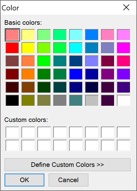
The Pick from model button enables you to define the color by picking the faces of the hole features.
When the color is defined using either of the two buttons, SolidCAM determines its RGB components and displays them in the Red/Green/Blue edit boxes. The chosen color is accepted, and when you click Find Holes, SolidCAM adds all holes with the specified color properties into the geometry.
In case of hole features consisting of several segments with different colors, the holes recognition is performed according to the color of the hole top segment regardless of the color properties of the lower segments.
|
Note that when the process of holes recognition takes place for the first time, the holes database is created containing all the colors of the hole features. If you change the colors after the holes recognition, these changes will not take effect unless you perform holes recognition again. If the color parameter is chosen by picking the color of a model entity, this color parameter becomes associative with the solid model. If the color is defined by choosing from the Windows palette, there is no associativity. |
2D Boundary
The 2D Boundary section enables you to specify the boundary geometry for the hole generation. The holes will be generated inside the specified 2D boundary. Select the 2D boundary check box and click Add to add a boundary using in the Geometry Edit dialog box.
Options
This button enables you to perform the holes recognition automatically in accordance with the specified filtering criteria.
This button enables you to define the geometry for Drill Recognition operations by picking the specific hole features directly on the solid model. When this option is chosen, the filtering capabilities are disabled.
In the Manual mode, a hole feature can be selected by picking its face or edge. When a face/edge is picked, SolidCAM checks in the HR database to which hole feature the selected entity belongs and adds the determined hole feature to the Holes Tree list.
|
The Auto and Manual modes can be combined, but note that if you use the Auto mode after the Manual mode, the selections made in the Manual mode will be cleared. |
This button performs the holes recognition and filtering of the recognized holes according to the criteria described above. The hole features matching the specified filter criteria will be displayed in the Holes Tree list.
|
Actually, the holes recognition is not performed each time when you click Find Holes. When the holes recognition is performed the first time for a specific Z-axis direction, the recognized holes data is stored in the database and can be used for further geometry definition. When you click Find Holes, SolidCAM retrieves the data from the database according to the filter settings and checks the synchronization between the data and the solid model. If the data in the database is not synchronized, a new holes recognition process is performed and filtering is reapplied. |
Use this option in combination with Find Holes if you need to perform again the holes recognition. Upon clicking Find Holes, SolidCAM processes new and overwrites the existing recognized holes data.
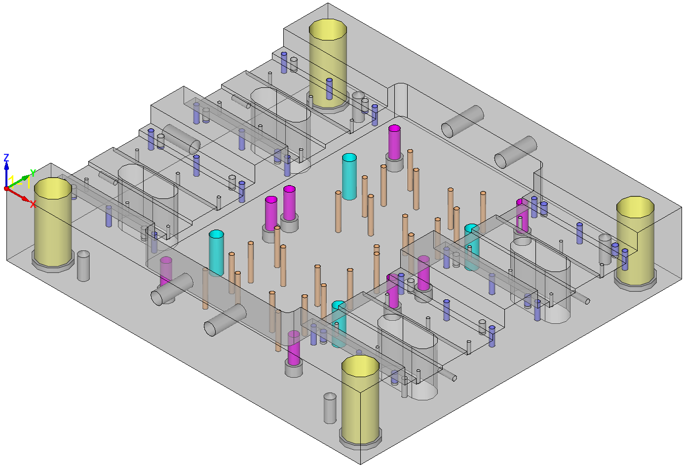
This button displays the current drill geometry based on selected items in the Holes Tree list and the initial machining sequence.
Click Resume to return to the geometry definition.
Holes Tree
In the Holes Tree list, the hole features are classified into Shapes and Groups. A Shape contains all the hole features with the same topology; within a Shape, the Groups include all the hole features with the same dimensions.
The check box near each item in the Holes Tree list enables you to select this item and include it in the current drill geometry. When a Group or a Shape is selected, all the hole features belonging to them are selected. The selected items are highlighted on the model.
|
You can select a group of holes using the mouse in combination with the Shift or Ctrl key. |
The right-click menu is available on the items in the list.
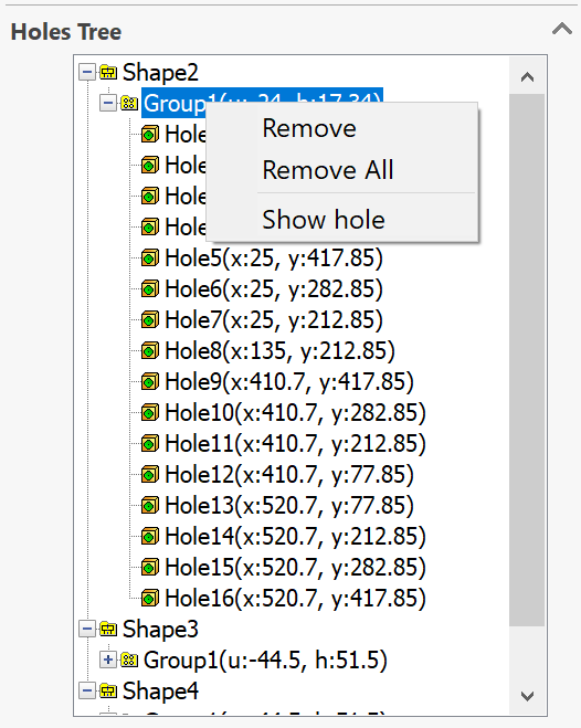
The Remove command enables you to remove the selected hole features from the list.
The Remove All command enables you to remove all the hole features from the list.
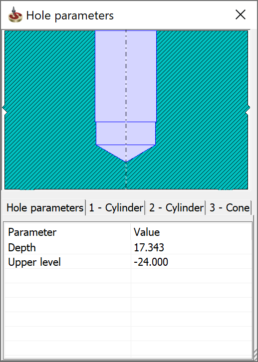
The Show hole command displays the Hole parameters dialog box.
Related Topics