Motion Control page
This page enables you to optimize the calculated tool path according to the kinematics and special characteristics of your CNC-Machine.
4th Axis
This section enables you to define the technological parameters of facial milling on Mill-Turn CNC-machines.
Indexial first rotation angle
The Indexial first rotation angle is added to extend the Working area of machines having a limitation in one of the Linear Axis in the working plane.
Enter the rotation angle manually in the edit box. The Part and the Rotary table will move by the angle specified in the edit box consequently extending the working area.
|
This option is useful for a Head-Table and Table-Table type CNC-machines. |
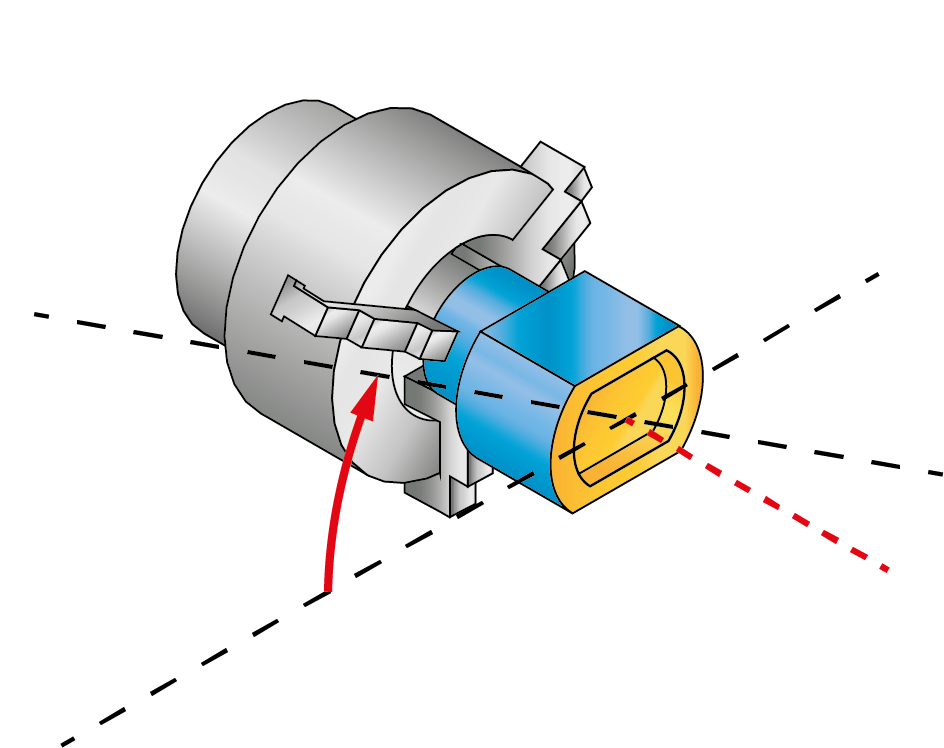
The Face Sim. option enables you to perform milling using the rotary axis by translating the linear movements in XY into the rotary-linear XC-movements.
|
Note that the technology offered by SolidCAM is universal: there is no limitations in terms of machines on which the part can be milled. To enable the possibility of milling the part on 3-axis Mill-Turn CNC-machines that support only the XZC coordinates where the movements along the Y-axis is impossible, you need to choose the Face Sim. option. |
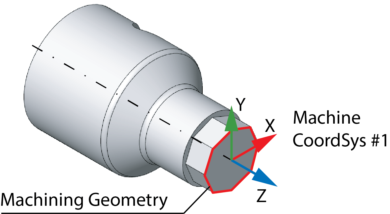
Coordinate type
This option enables you to determine whether the GCode will consist of split blocks or blocks in polar/Cartesian coordinates:
Polar
When this option is chosen, the tool path is calculated in polar coordinates.
Cartesian
This option appears only if the cartez_4x = Y is defined in the PRP file. The tool path lines and arcs are calculated in Cartesian coordinates; the CoordSys position is zero for linear coordinates. The milling is processed using the rotary axis by translating the linear movements into the rotary-linear movements according to the plane.
Plane
The option of Plane, allows you to choose the appropriate plane i.e, XC,YC, or ZC.
5th Axis
For a 5-axis machine, the tool axis vector can always be mapped into two different angle pairs. During the tool path generation, SolidCAM calculates for each tool axis orientation both of these two angle pairs; only one of the two has to be chosen for the GCode generation. The following options enable you to choose the angle pair.
First/Second angles pair
Some machines can only use one of the angle pairs due to mechanical limitations. In this case, the angle pair will be chosen as the First angles pair or Second angles pair.
Approximation of arcs
This option enables you to control the process of arcs approximation at the operation level.
The Approximate arcs by lines check box that enables you to control the existence of arcs in the GCode output for the current operation.
When this check box is selected, SolidCAM approximates all tool path arcs by lines using the Tolerance defined in the edit box. The precision of the approximation depends on the Max Chord Length and Max Arc Angle parameters located in the VMID file; the resulting GCode does not contain arcs.
When this check box is not selected, the resulting GCode might contain arcs.
Point interpolation
Interpolation for distance
Using this option, SolidCAM enables you to perform interpolation for the linear tool movements. When this option is active, a new interpolated tool position is defined at each distance, defined by the Interpolation for distance parameter.
E.g. when the linear tool movement is performed from 0, 0, 0 to 0, 0, 100 and the Interpolation for distance option is used with the Distance value of 10, SolidCAM adds 9 tool positions between start and end positions (0, 0, 10, then 0, 0, 20 etc.).
Rapid feed rate moves
When this option is selected, a new interpolated tool position is defined also for rapid moves.
Machine Limits
With this option, SolidCAM enables you to use the machine limits defined within the machine definition to limit the tool path movements in translation and/or rotation axis.
The following options of machine limits use are available:
No limits
All the machine limits defined in the machine definition are ignored.
Translation limits
SolidCAM uses the machine limits defined in the machine definition for translation movements.
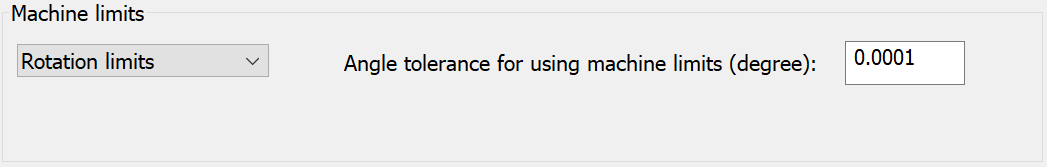
Rotation limits
SolidCAM uses the machine limits defined in the machine definition for rotation movements.
All limits
SolidCAM uses the machine limits defined in the machine definition for both translation and rotation movements.
When machine limits are used, the calculated tool path is checked in order to avoid exceeding the machine limits. The check is performed using the angle tolerance defined by the Angle tolerance for using machine limits parameter.
Related Topics