Spiral open slot wide
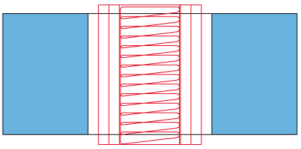
This ToolBox Cycles strategy enables you to perform the machining of wide open slots. The first cutting pass is performed in the spiral manner along the determined spine of the slot, and then the machining of the slot walls is performed by a number of profiles equidistant to the slot geometry.
Geometry definition
The strategy provided by this sub-operation can be performed only on a pair of open chains, similar to the Simple slot and Spiral open slot sub-operations; accordingly, the geometry should contain at least two open chains. The geometry containing only closed chains is considered as unsuitable. The geometry containing more than only one open chain is considered as unsuitable. The geometry containing more than one open chain is considered as suitable. The mixed geometry containing a number of open and closed chains is considered as suitable, if there are more than one open chain. In such geometry, all the closed chains are ignored during the tool path calculation. When the geometry contains an odd number of open chains, the last chain (not included into a pair of chains) will be ignored.
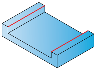
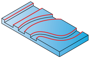
This sub-operation is intended to perform the open slot machining. The open slot shape should be chosen in the manner as shown below.
When the geometry is defined, SolidCAM chooses the first and the second open chains and forms the first pair. The machining of the first slot will be performed using this pair of chains. All the other chains are divided into pairs similarly.
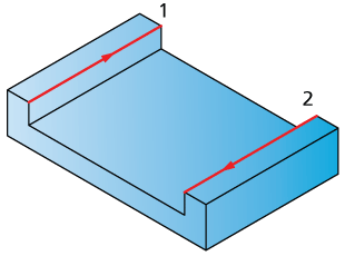
For each such pair, the direction of the first chain is determined. This direction defines the direction of the machining. The machining is performed between two chains in the climb manner. The direction of the second chain is ignored.
|
The ideal slot shape intended to be machined with this sub-operation consists of two equidistant walls.
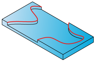
The example below illustrates the shape that is not intended to be machined with this sub-operation, therefore choosing such geometry can cause errors during tool path calculation.
|
Technological parameters
Rough
SolidCAM enables you to perform the open slot machining in a number of roughing and finishing cutting passes distributed along the tool axis.
Step down
The distance between two successive cutting levels is defined by the Step down parameter. The Equal step down option enables you to define a number of evenly distributed cutting levels. SolidCAM automatically calculates the actual step down to keep an equal distance between all passes, while taking into account the specified Max. Step down value so that it is not exceeded.
Spiral cuts & Parallel cuts
The tool path consists of a number of spiral cuts (controlled by the Spiral cuts section) and a number of cuts along the geometry (controlled by the Parallel cuts section).
The Spiral cuts section provides you with the Step over and Moat width parameters to control the spiral tool path that consists of several recurrent spiral cutting passes. The Step over parameter enables you to define the distance between two successive cutting passes. The Moat width parameter defines the width of the spiral cutting pass.
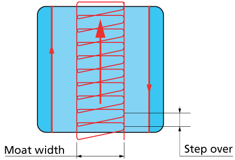
The Retract Height parameter enables you to define the height above the cutting level where the retract motion is performed during the spiral cutting.
The Parallel cuts section enables you to control cutting passes performed along the geometry. The Step over parameter defines the distance between two successive cutting passes along the geometry.
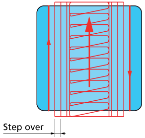
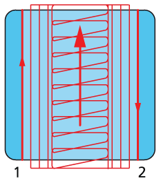
The Direction section enables you to define the tool path ordering and direction. Generally, all the cutting passes performed along the geometry chains are located at both sides of the spiral cutting pass. During the machining, SolidCAM performs the machining of the cutting passes located between the first chain and the spiral cutting pass and then machines the cutting passes located between the spiral cut and the spiral cutting pass.
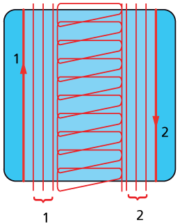
The passes are ordered starting from the spiral cut in the direction of the geometry chains.
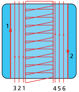
When the One way option is chosen, SolidCAM performs all the cutting passes along the geometry chains in a direction that enables the tool to maintain the climb milling for all the cuts. The cutting passes are connected via the Clearance level: when a specific cutting pass is completed, the tool ascends to the Clearance level. At this level, the tool moves to the start position of the next successive cutting pass. At this point, the tool descends to the cutting level and starts the cutting in the climb direction.
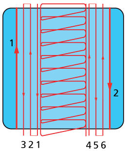
When the Zigzag option is chosen, SolidCAM changes the direction for all the even cuts. Therefore the machining is performed with the combination of climb and conventional milling. Note that the first cutting pass (closest to the geometry chain) is performed in climb milling. When a specific cutting pass is finished, the tool moves directly to the end of the next successive cutting pass and performs its machining in the opposite direction.
Extension
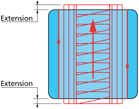
During the machining, the tool path is extended over the slot entrance and exit in order to perform the approach to the cutting area from the outside and exit from the material at the end of the slot. The Extension section enables you to define the tool path extension either by percentage of the tool diameter (the % of tool diameter option) or by value (the Value option).
Offsets
This section enables you to define Wall and Floor offsets for this sub-operation. The Wall offset is applied to the walls of the slot; the specified offset is left unmachined during the current sub-operation. The Floor offset is applied to the floor of the slot; the specified offset is left unmachined during the current sub-operation. When the Floor offset value is specified, SolidCAM performs the machining by the Z-levels defined with the Step down parameter. The machining is performed until the Floor offset level.
Compensation
If the Compensation check box is selected, the tool radius compensation options G4x of the CNC-controller are used in the GCode.
Finish
The Wall finish option enables you to perform a final finishing pass cleaning the walls. You can specify the Step down value in a separate field.
The Floor finish option enables you to perform a final finishing cut cleaning the floor.
Sort by
This option enables you to choose the method of sorting the cutting passes.
When the Passes option is chosen, the tool completes the machining of a specific Z-level for a specific chain and then moves to the next Z-level of the same chain. When machining of all the Z-levels of a specific chain is completed, the tool moves to the next chain.
When the Slices option is chosen, machining of all chains at a specific Z-level is performed; when machining of this level is completed, the tool moves down to the next level, and so forth.
Tool path calculation
During the tool path calculation, SolidCAM determines the area between two chains to be machined. Also SolidCAM determines the spine curve of the slot.
At the next stage, the spiral tool path is generated to “open” the area between chains. The spiral tool path is generated along the spine curve in the direction of the first chain. The spiral tool path is controlled by the Moat width and the Step over parameters.
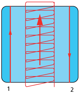
The spiral tool path consists of several recurrent cutting passes; each of them performs the machining in the climb manner. When the spiral cutting pass is generated, SolidCAM generates a number of equidistant cutting passes along the chain geometry. These cutting passes are also performed in the climb manner taking into account the direction of the first geometry chain.
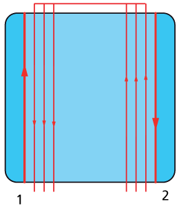
The distance between two successive cutting passes is controlled with the Step over parameter.
The resulting combined tool path consists of spiral cutting pass and a number of cutting passes along the geometry.