Area
The Area section enables you to define the cutting area on the drive surface.
The Type list enables you to choose the following options:
Full, avoid cuts at exact edges
Full, start and end at exact surface edges
Limit cuts by one or two points
|
All of these options are unavailable with the Projection technology. |
Full, avoid cuts at exact edges
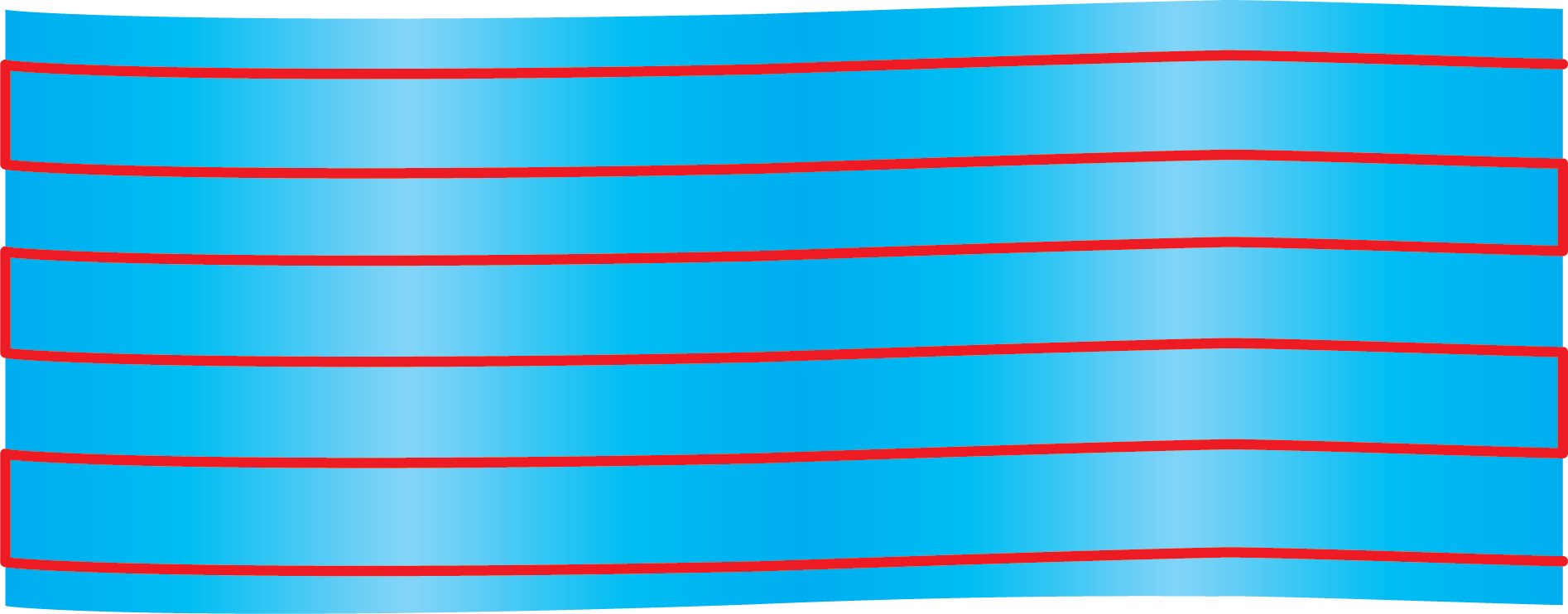
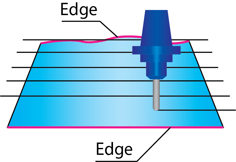
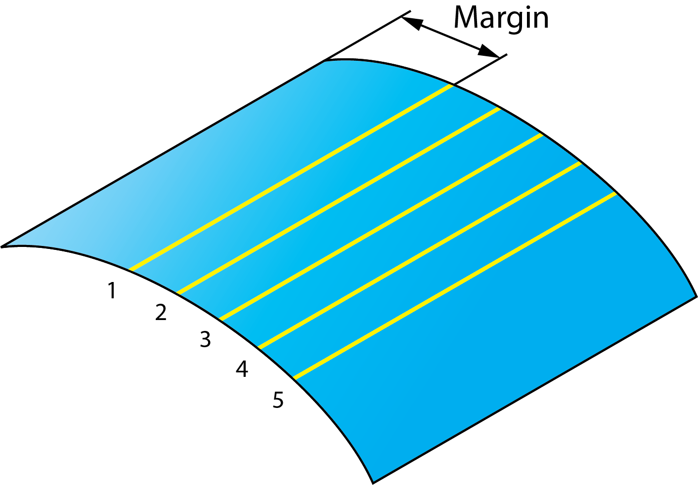
This option enables you to generate the tool path on the whole drive surface avoiding the drive surface edges. With this option, the minimal distance between the edge and the tool path is equal to half of the Max. Step over. |
 |
| This option can be used when the boundary of the drive surfaces is not smooth and has gaps. The half of the Max. Step over offset from the surface edge enables you to compensate these defects of the surface. In case of large gaps, SolidCAM enables you to handle them using the Gap along cuts option. | |
When the tool is oriented normally to the drive surface, make sure that the tool diameter is greater than half of the Max. Step over. Otherwise, unmachined areas are left at the drive surface edge. The image illustrates the use of this option. Note that the machining does not start at the exact edge of the surface. Therefore, the shape of the upper edge does not influence the tool path. |
 |
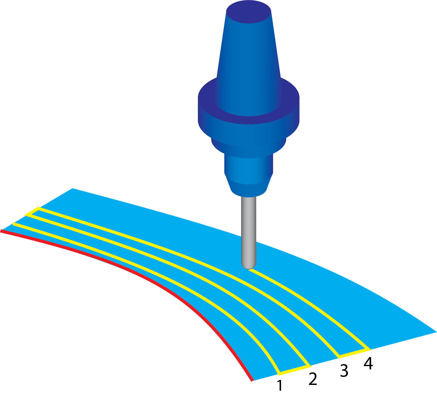
Full, start and end at exact surface edges
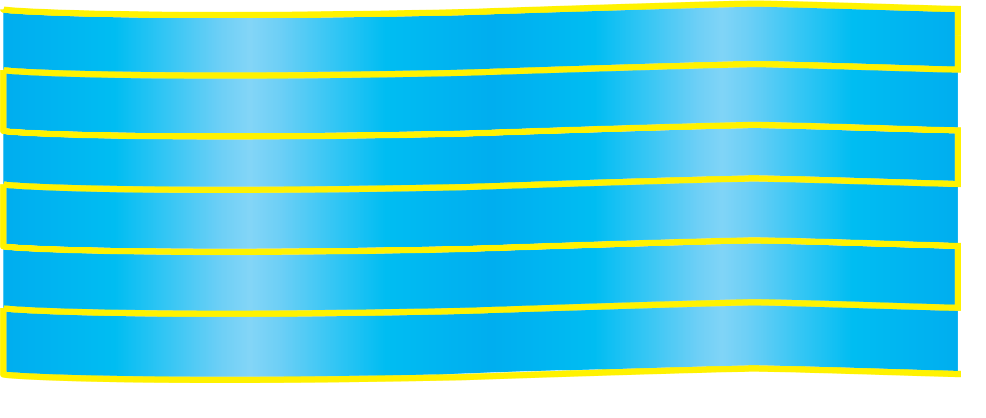
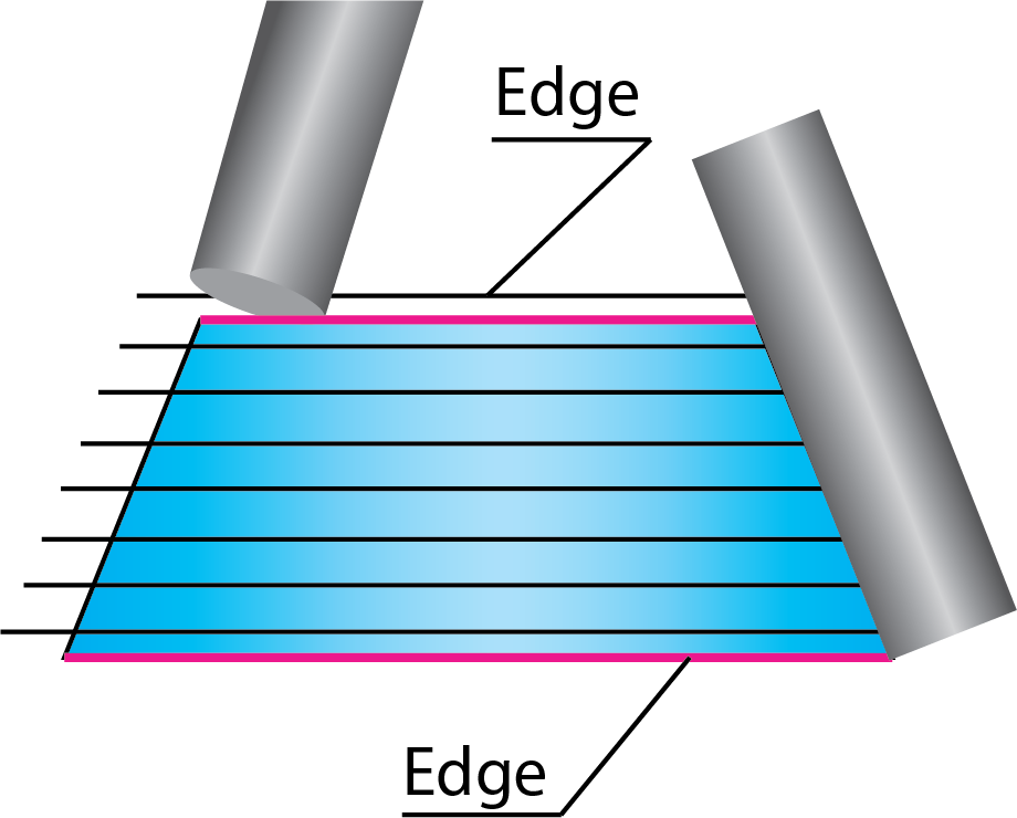
With this option, the tool path is generated on the whole surface starting and finishing exactly at the drive surface edges or at the nearest possible position. |
|
||
Make sure that the surface edges are perfectly trimmed. Gaps cause unnecessary air movements of the tool during the machining, therefore the Full, avoid cuts at exact edges option is preferable. |
|
||
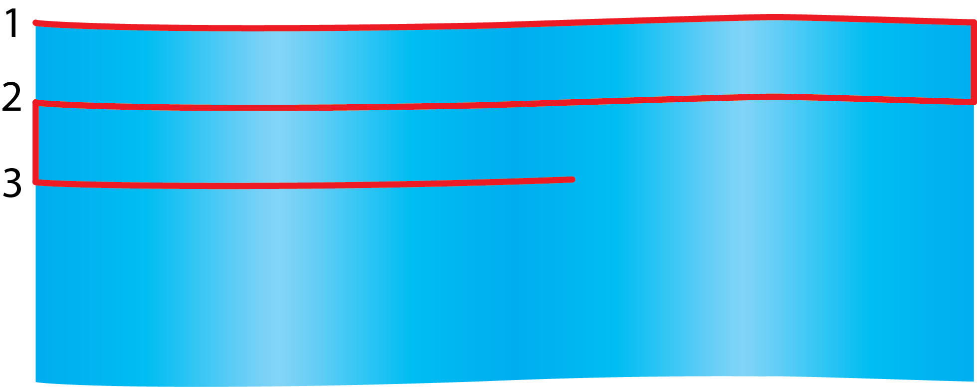
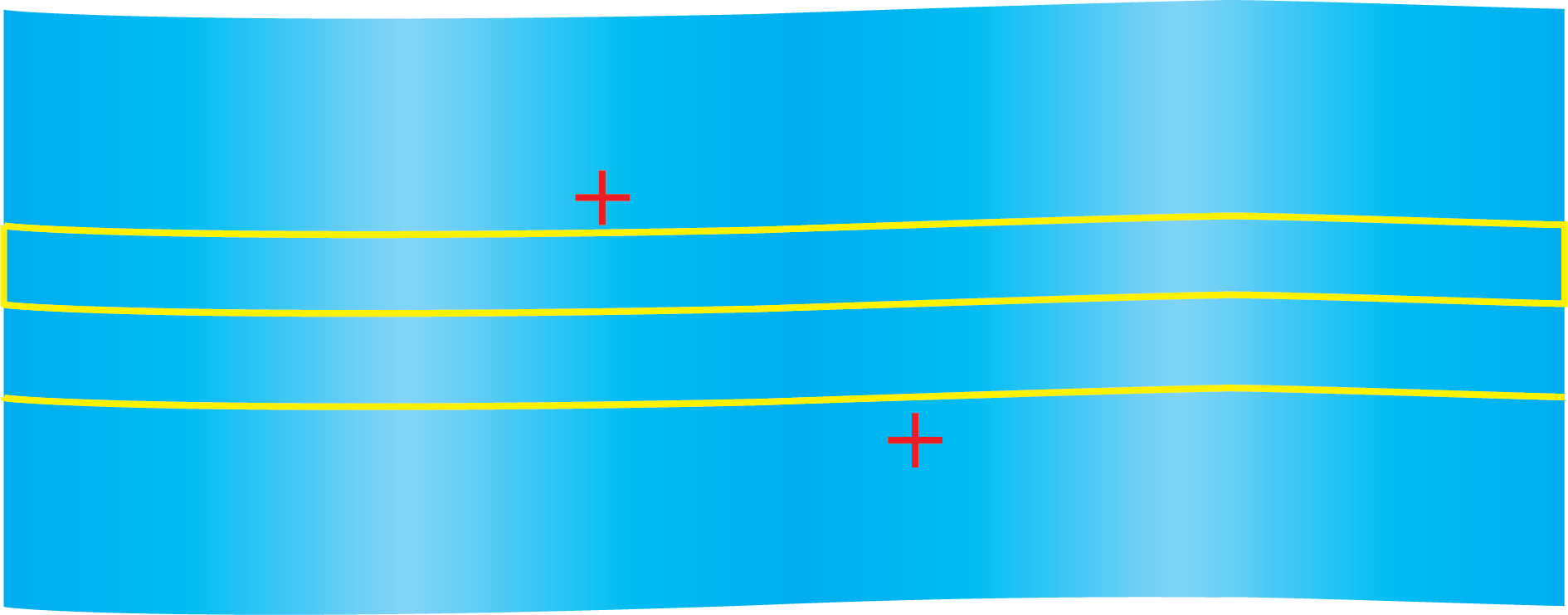
The number of cuts depends on the Max. Step over value. Since the first and the last cuts are located exactly on the drive surface edges, SolidCAM modifies the specified Max. Step over value to achieve equal distance between the cuts. The modified Max. Step over value used for the tool path calculation is smaller than the specified one. You can define margins for the tool path calculation when working with the following strategies: Morph between two boundary curves, Parallel to curve, Parallel to surface, and Morph between two adjacent surfaces.
|
|||
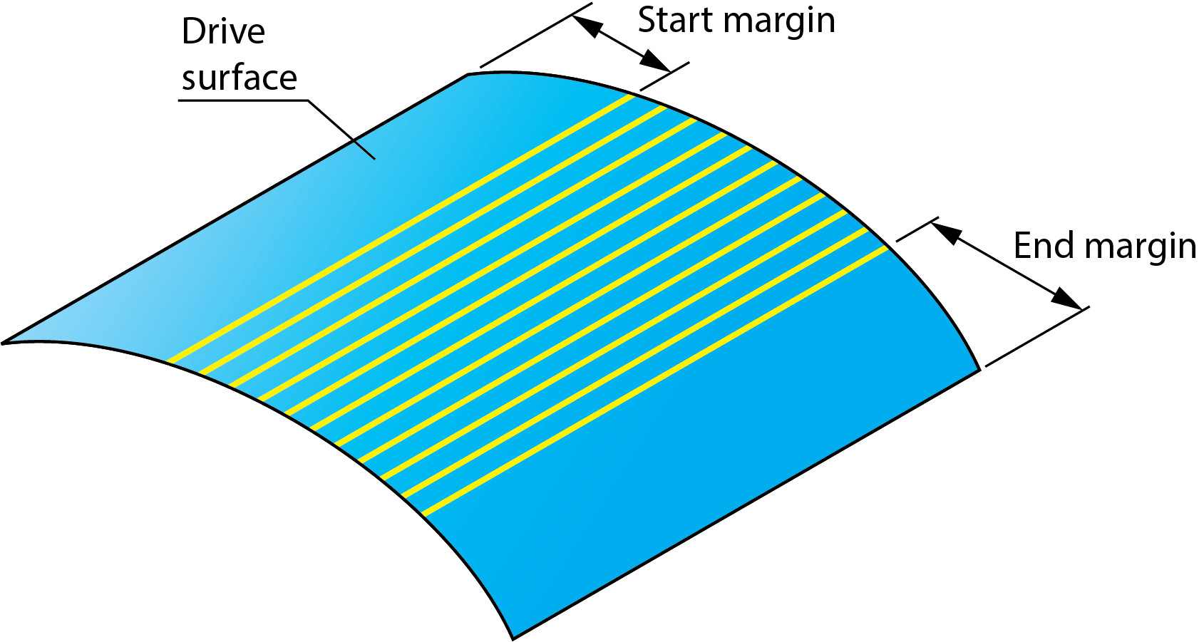
Click Margins. The Margins dialog box is displayed. This dialog box enables you to define a margin for the drive surface edges. The machining starts and finishes at the specified distances from the drive surface edges. Advanced parameter for marginsTool path strategies that use edge curves and surfaces sometimes encounter difficulties since CAD systems deliver the drive surfaces and the edge geometry (curves or surfaces) only within accuracy. |
|
||
If you would like to start the tool path exactly at the zero distance to the edge geometry, this is problematic, because the geometry can never be exactly aligned. To avoid this problem, SolidCAM provides you with the Advanced parameter for margins option.
The Additional margin to overcome surface edge inaccuracies parameter enables you to compensate the inaccuracy of the CAD model edges. For example, to get the tool path at the 5 mm distance from the geometry, set the margin to 4.97 mm and the Additional margin to overcome surface edge inaccuracies to 0.03. The Add tool radius to margins option enables you to expand the cutting area, which is defined by margins, by the tool radius distance.
|
|||
Determined by number of cuts
This option enables you to limit the tool path by a number of cuts. The Number of cuts parameter defines the number of cutting passes. |
 |
||
When the Parallel to curve/Parallel to surface technology is chosen for the geometry definition, the Determined by number of cuts option generates the following tool path: the tool starts machining from the defined curve/surface and performs the number of cuts defined with the corresponding parameter.
|
|||
Parallel to curve |
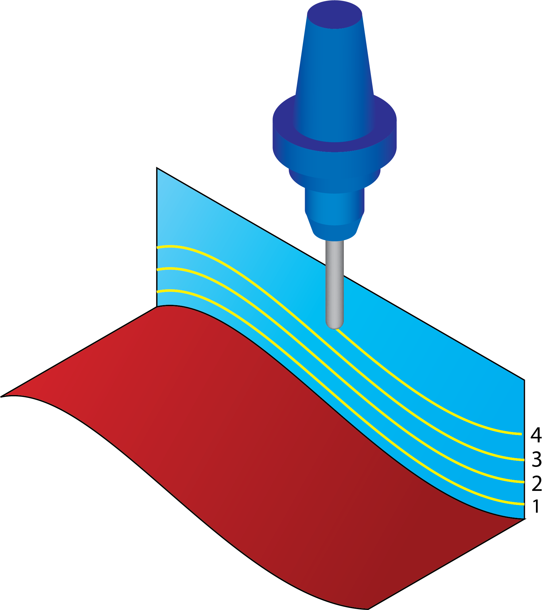
Parallel to surface |
||
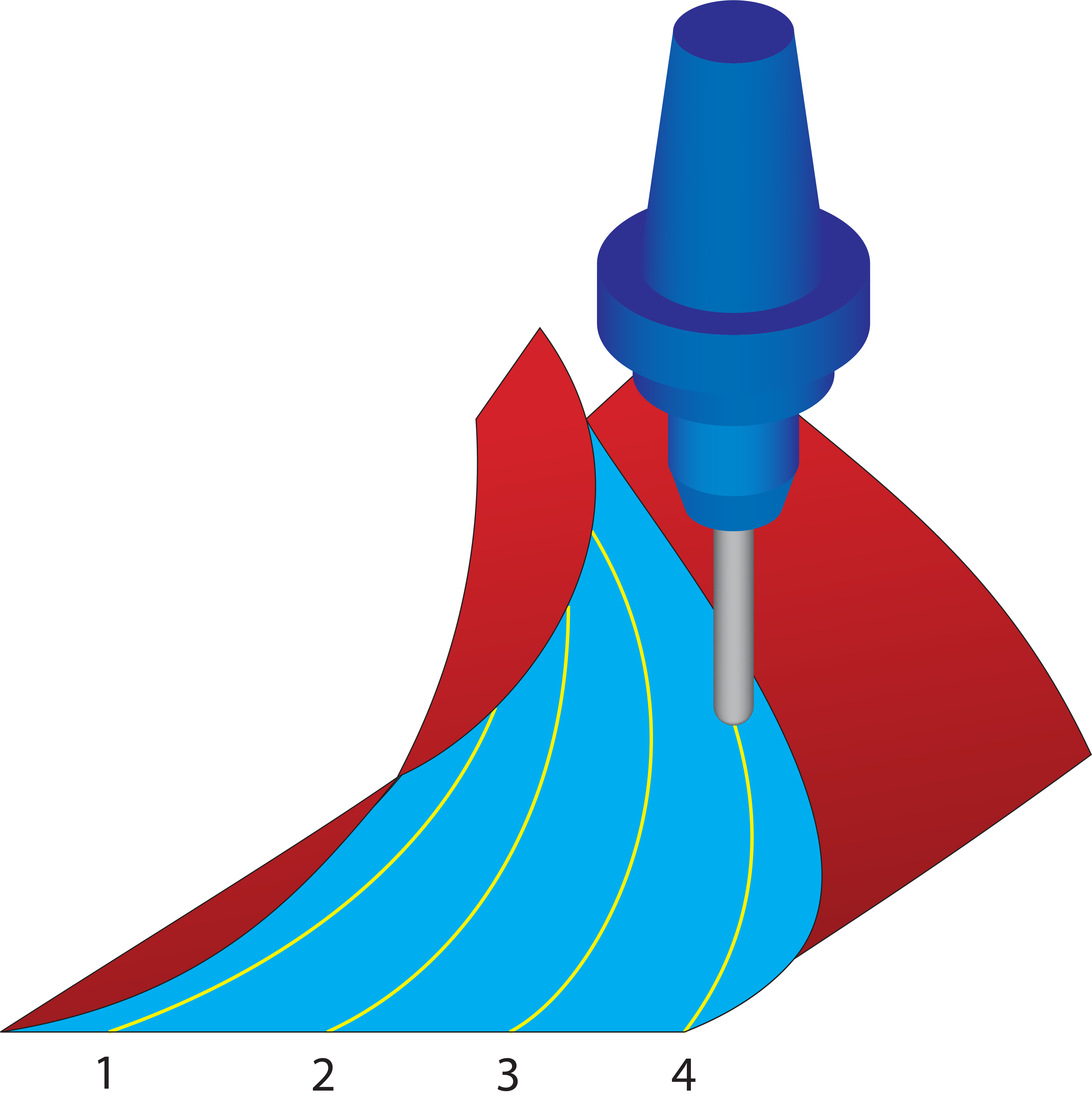
When the Morph between two adjacent surfaces technology is chosen for the geometry definition, the area between the defined surfaces is divided by the number of cuts in such a manner that the first cut is performed at the Start edge surface, and the last cut at the End edge surface. |
 |
||
|
|||
SolidCAM enables you to define a margin, shifting the first cut location. Click the Margins button to display the Margins dialog box. The location of the first cut is shifted by the distance specified by the Start margin parameter.
|
 |
||
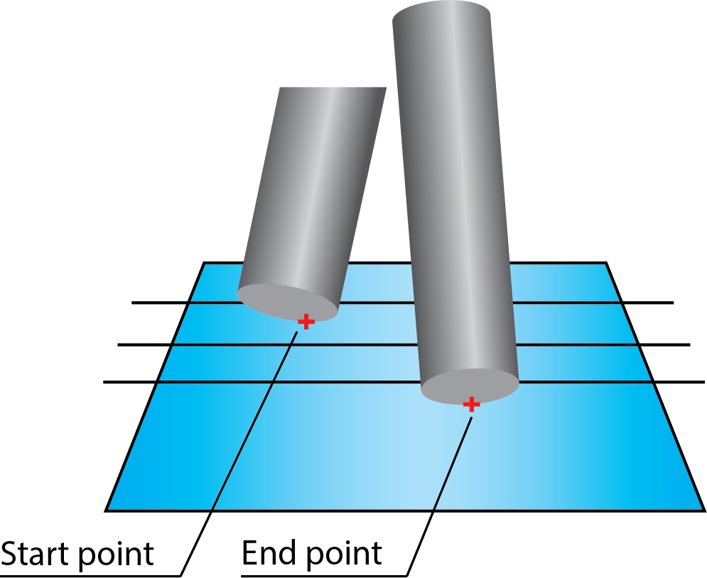
Limit cuts by one or two points
This option enables you to limit the tool path by one or two points. |
 |
||
Click Points to define the limiting points with the Limit Cuts Between 2 Points dialog box. This dialog box enables you to enter the coordinates of the limiting points or define them directly on the solid model.
|
|||
|
 |
||
|
All of these options are unavailable with the Projection technology. |
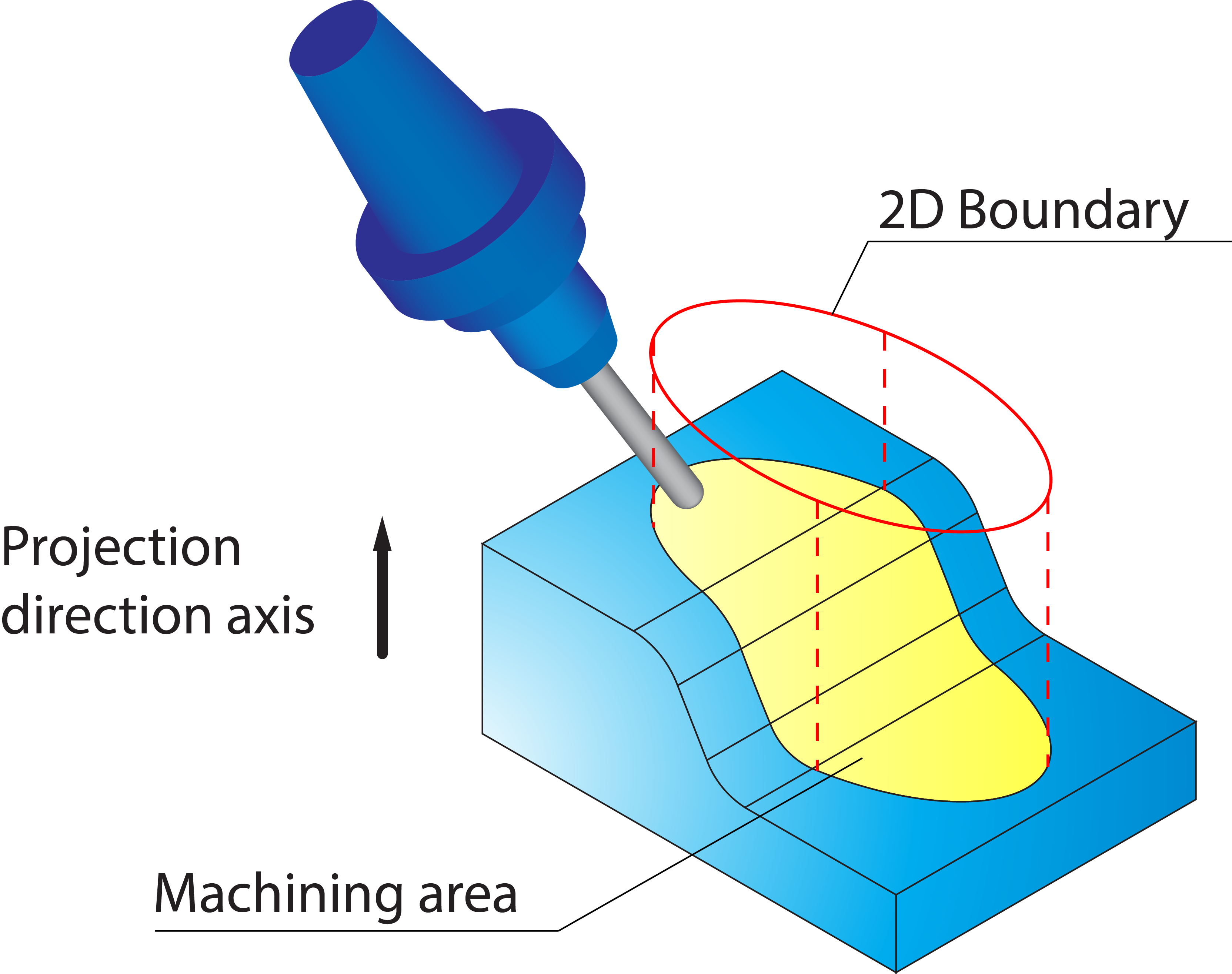
Use 2D Boundary
SolidCAM provides you with a functionality to limit the machining to specific model areas. The machining limitation is performed by a planar boundary that is projected on the model. The projected boundary is “virtually” trimming the drive surfaces. All the contact points of the tool and drive surfaces are enclosed by this projected boundary.
2D Boundary curves
SolidCAM enables you to define a boundary based on a Working area geometry (closed loop of model edges as well as sketch entities).
Both New ![]() and Edit
and Edit ![]() display the Geometry
Edit dialog box that enables you to define and edit the geometry.
display the Geometry
Edit dialog box that enables you to define and edit the geometry.
Show enables you to display the already defined boundary directly on the solid model.
Projection direction
When a planar boundary is defined, SolidCAM automatically projects the geometry onto the solid model. The direction of the projection is defined by a vector. SolidCAM enables you to choose an axis of the Coordinate System as a projection direction vector or define a vector by an end point (the start point is automatically considered to be located in the Coordinate System origin). |
 |