General
The iMachining technology automatically calculates the General parameters by determining the best method to enter and exit the cut for the operation.
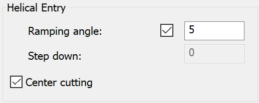
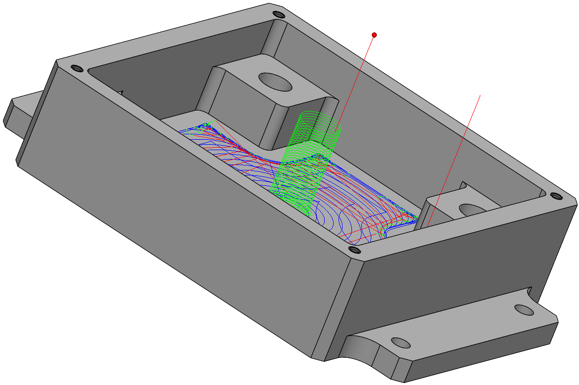
Helical Entry
When the geometry is defined as a closed pocket, the tool enters the material in a spiral movement according to the Helical Entry parameters.
Calculating the helical diameter
The helical diameter is hard-coded at 90% of the tool diameter, providing a descending helix of maximal size while maintaining enough overlap through the center. After the helical ramping is performed, the diameter (d) of the entry hole can be calculated according to the formula d = (0.9 × Diameter)+Diameter.
Upon calculating the tool path, if the helical entry cannot fit in the designated area, 70% of the tool diameter is then used to calculate the helical diameter.
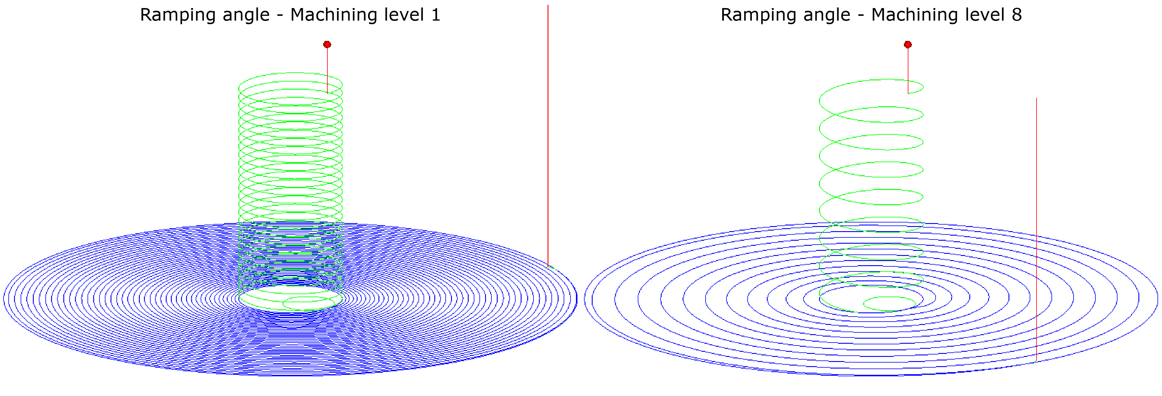
Ramping angle
This parameter defines the aggressiveness of the descent angle by which the tool enters the material. By default, the iMachining Technology Wizard automatically calculates the helical cutting conditions based on material hardness and aggressiveness of the Machining level slider.
|
Warning: When using more aggressive values, cooling can become a concern. Larger values will generate more heat and proper cooling should be applied when necessary. |
An override check box is provided so the Ramping angle value can be set manually, in the instance you want the tool to perform a helical entry at an aggressiveness unrelated to the position of the Machining level slider.
Ramping radius
This parameter, which is not visible within the operation, is used to calculate the size of the helical diameter of the tool path as well as the diameter of the entry hole after the helical ramping is performed.
Initially, 90% of the tool radius is used for the helical diameter calculation. If the tool radius is Rad, the helical diameter (hd) can be calculated according to the formula hd = (0.9 × Rad) + Rad (equivalent to 190% of the tool radius). The percentage is hard-coded to provide a descending helix of the maximal size, while also maintaining enough overlap through the center.
The diameter (d) of the entry hole can then be calculated according to the formula d = 2 × hd.
Upon calculating the iMachining tool path, if the helical entry cannot fit in the designated area(s), 170% of the tool radius is instead used for the Ramping radius calculations.
The iMachining technology now provides optional minimum percentages that can be used for the Ramping radius calculations. The Minimum Helical Ramping Radius is a setting that can be modified in the following two ways:
1. Per project in the Part Settings dialog box > iMachining page
2. Globally in the SolidCAM Settings dialog box > iMachining page
Center cutting
This option is enabled by default (since it is more common to use a tool with center cutting capabilities).
Tool with Center cutting capabilities
For tools with center cutting capabilities, the working order is as follows:
From the Clearance level, the tool descends to the Safety distance above the Upper level.
The tool performs a helical entry into the material at the specified Ramping angle until the operation Step down depth is achieved, and then all material at that depth is machined.
When the machining is completed at the operation Step down depth, the tool retracts up to the Clearance level and repositions itself to the original start point, and then steps 1 and 2 above are repeated until the total depth is achieved.
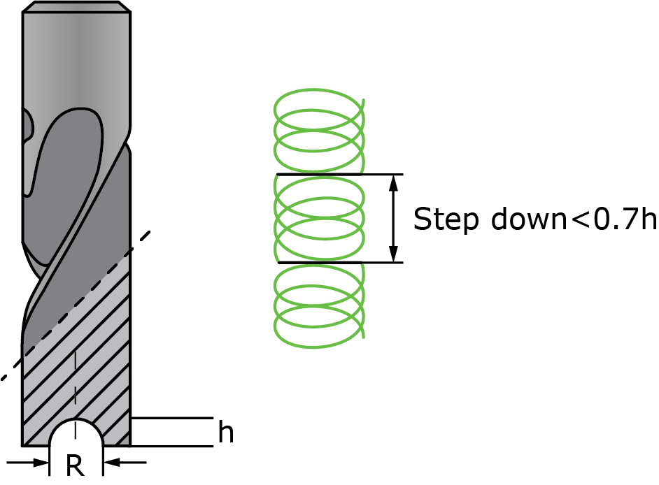
The Center cutting option works in conjunction with the Step down parameter, which defines the depth at which the tool stops ramping down into the material; and at this depth, the tool clears a circular path in order to make the floor flat.
When this option is disabled, the Step down field is open to be edited, where you have to enter a calculated value based on the attributes of the tool without center cutting capabilities.
If your tool does not have center cutting capabilities, you must disable the Center cutting check box.
Tool without Center cutting capabilities
For tools without center cutting capabilities, the working order is similar to a tool with center cutting capabilities plus the following differences:
From the Clearance level, the tool descends to the Safety distance above the Upper level.
The tool performs a helical entry into the material at the specified Ramping angle until the Step down parameter is reached, and then the tool clears a circular path in order to make the floor flat. This process is repeated until the operation Step down depth is achieved.
When the operation Step down depth is achieved, all material at that depth is machined.
When the machining is completed at the operation Step down depth, the tool retracts up to the Clearance level and repositions itself to the original start point, and then steps 1 through 3 above are repeated until the total depth is achieved.
In pocket positioning
Z clearance
This parameter defines the height in which the tool is picked up off the floor when repositioning from one cut to the next.
![]()
Detour length
When the ![]() mode is enabled in the Operation dialog box, the Detour length slider
appears on the Link page.
mode is enabled in the Operation dialog box, the Detour length slider
appears on the Link page.
This slider enables you to adjust the distance in which the tool is allowed to travel alongside the material when repositioning from one cut to the next. The Detour length value is automatically calculated to keep the tool down as much as possible in order to reduce retracts and long position moves.
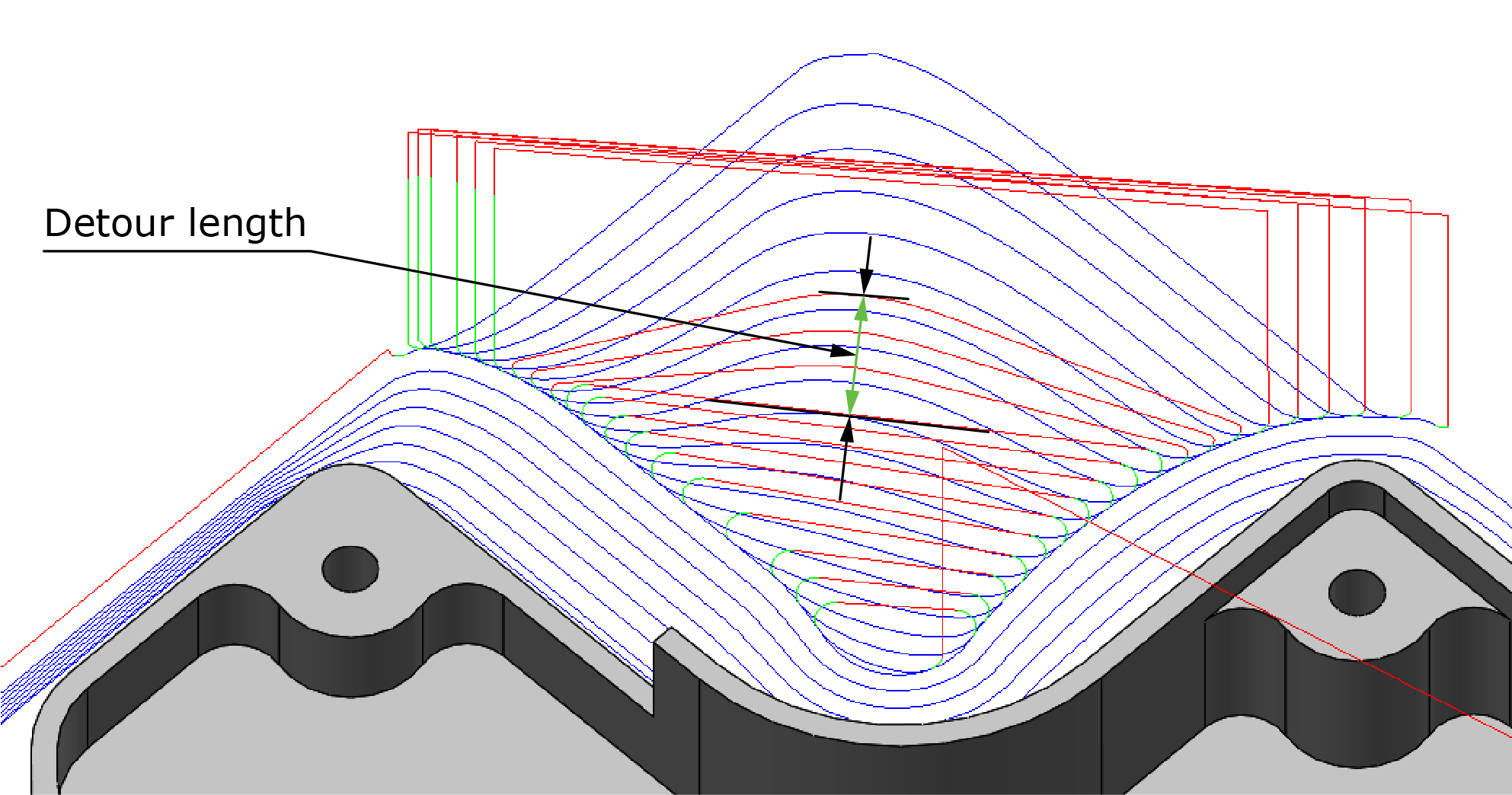
If the Detour length required to reach the next pass exceeds the specified value, the tool retracts up to the Clearance level and repositions via a straight line movement.
Max. arc size
When the ![]() mode is enabled in the Operation dialog box, the Max. arc size slider
appears on the Link page.
mode is enabled in the Operation dialog box, the Max. arc size slider
appears on the Link page.
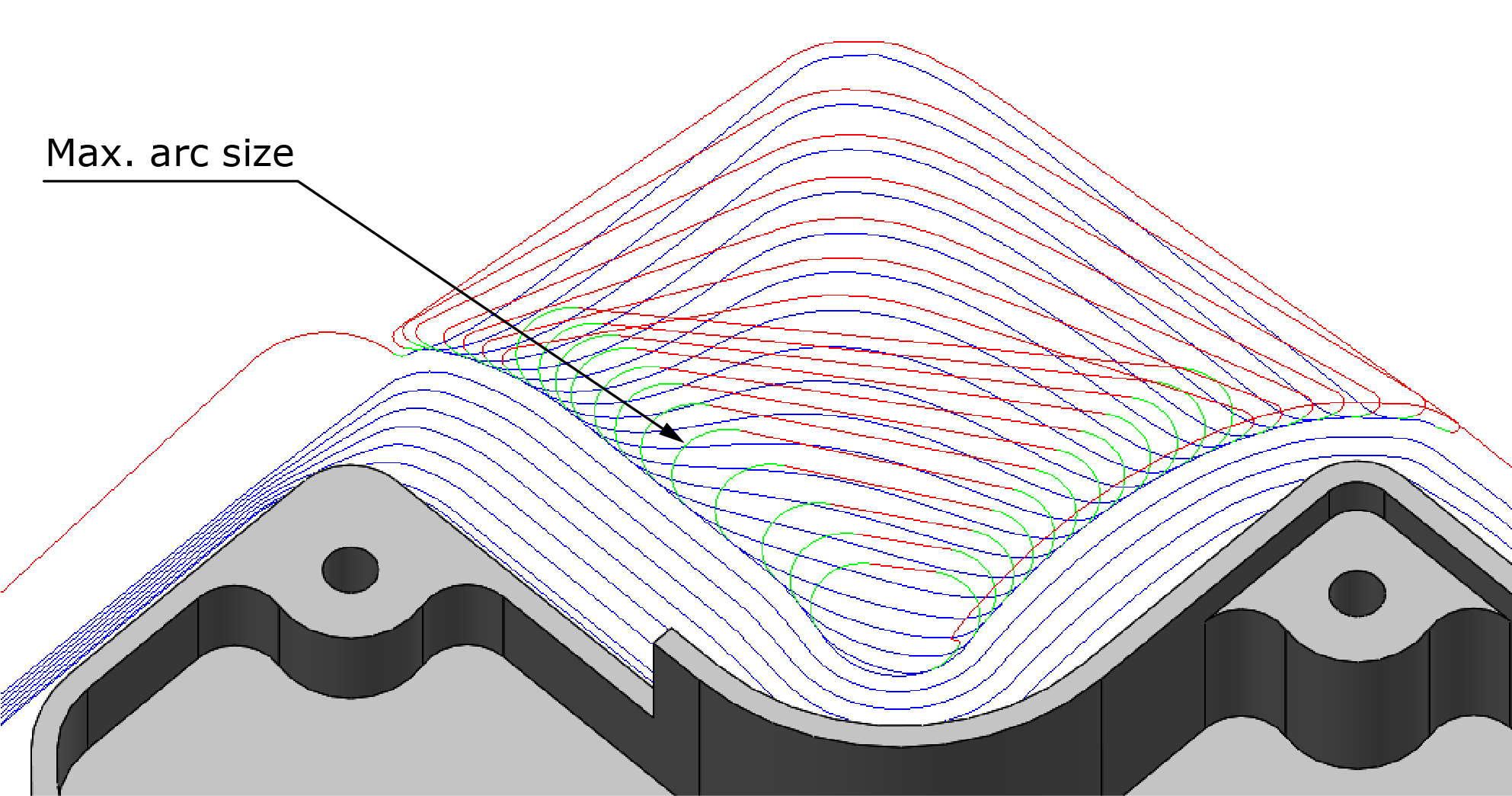
This slider enables you to adjust the maximum size of the 3D arc that is used when repositioning from one cut to the next. The Max. arc size value is based on the current tool diameter.
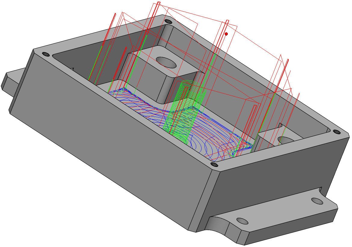
In iMachining 2D, the 3D Positioning option eliminates retracts and optimizes the iMachining tool path. 3D Positioning uses the stock model that is dynamically updated after each cutting move. The major impact seen is when the tool retracts to a position between roughing and finishing tool paths and during re-positioning between wall and floor finishing passes. This option is On by default for a newly added operation and Off for an existing operation.
 |
 |
3D Positioning Off |
3D Positioning On |
|
3D Positioning feature works when you use the following iMachining Feature Recognition modes : Feature Recognition by Faces, Feature Recognition by Chains and Outside feature Recognition. |
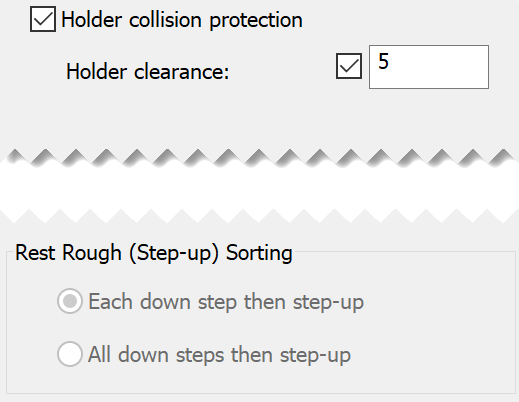
Rest Rough (Step-up) Sorting
In iMachining 3D, there are two methods for choosing the order of roughing and rest roughing tool path passes:
- Each down step then step-up (default selection) – this option successively performs the Step-up rest roughing after each Step down roughing pass is achieved.
- All down steps then step-up – this option performs the Step-up rest roughing after the final Step down roughing pass is achieved.
|
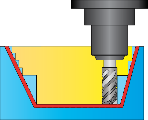
When using Holder collision protection, Each down step then step-up remains the default selection and cannot be changed.
Each down step then step-up provides maximum clearance for the tool holder, which allows the extension of the tool from the holder to be short and strong. In most cases, all material that needs to be removed and that can be removed by the operation is machined.
|