Technology
The iMachining technology automatically calculates most of the technological parameters according to many factors. You can modify the defaults as well as define tool path parameters and options that are specific to the iMachining 2D or iMachining 3D Technology types.
Step down
The Step down defines the axial depth of cut for the operation. The value displayed in the locked text field corresponds to the largest Step down (if there are multiple steps with different depths) shown in the output grid on the Technology Wizard page.
When the Wizard is ![]() in the Operation dialog box,
the Step down is shown with a
in the Operation dialog box,
the Step down is shown with a ![]() icon because it needs to be synchronized with the selected set of Cutting
conditions. If you want to manually enter a preferred value, the
Wizard can be turned
icon because it needs to be synchronized with the selected set of Cutting
conditions. If you want to manually enter a preferred value, the
Wizard can be turned ![]() to open the field for editing.
to open the field for editing.
|
When using the iMachining technology, it is highly recommended to leave the Wizard On and utilize the optimal step downs that are provided. The Wizard automatically calculates these values and manages synchronization across step down, step over, spindle speed and feed rate. |
Rest Rough (Step-up)
In iMachining 3D, the parameters used for calculation of the Step-up tool path passes will appear in this section of the Operation dialog box according to the specified Technology type:
Ignore closed pockets
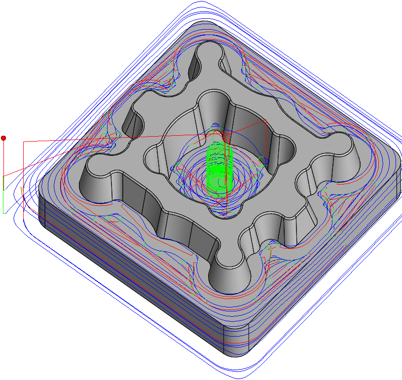
iMachining 3D analyzes the Target model and then recognizes all its features and depths automatically. A single iMachining 3D operation removes all the volumes of material that can be removed using the selected tool. The iMachining 3D tool path consists of both Step down (roughing) and Step-up (rest roughing) passes.
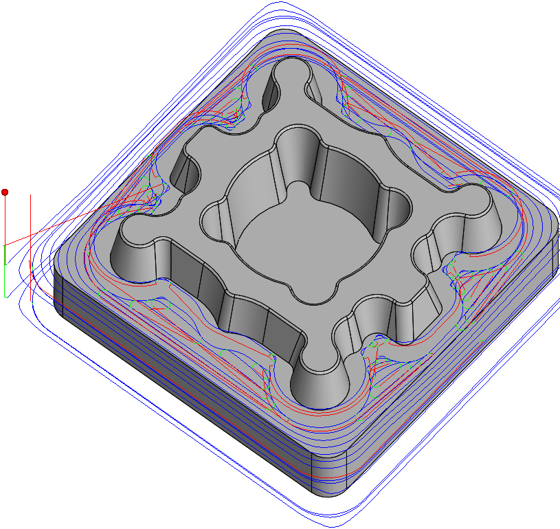
When this option is enabled, iMachining 3D eliminates the roughing and rest roughing tool path passes contained in closed pocket areas (e.g., cavity features of a mold core), leaving only those volumes unmachined.
 |
 |
Ignore closed
pockets |
Ignore closed
pockets |
This option enables you to machine all semi-open and open pocket areas with one iMachining 3D operation using your high performance end mill. For the closed pocket areas that require a helical entry, you can define a separate operation using a standard end mill.
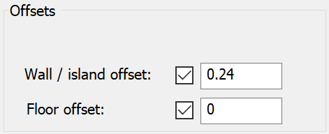
Offsets
This section enables you to specify the Offsets for the operation relative to the iMachining 2D or iMachining 3D geometry selection.
iMachining 2D Offsets
Wall/island
offset – this parameter defines the machining allowance that will
remain on the pocket walls/islands after a roughing (iRough) or rest machining
(iRest) operation. For iRough + iFinish and iFinish, the finishing is
executed in the same operation to remove the allowance.
For iRest and iFinish, the Wall/island offset value is inherited from the
Previous wall offset of the Parent operation
with an available override.
Floor offset
– this parameter defines the machining allowance that will remain on the
pocket floor after the operation, unless the Floor option is enabled in the
Finish section.
For iRest and iFinish, the Floor offset value is inherited from the Previous
floor offset of the Parent operation
with no available override.
Based on the diameter of the tool, iMachining provides initial default values for the Wall/island offset and Floor offset parameters to minimize your operation entries. In addition, those values are dynamically updated when the tool diameter is changed or a new tool (with a different diameter) is selected for the operation.
For milling tools with a diameter > 6 mm (0.25 in): |
Wall/island offset and Floor offset both have a default input value of 0.3 mm (0.01 in). |
For milling tools with a diameter ≤ 6 mm (0.25 in): |
Wall/island offset and Floor offset both have a default input value of 0.15 mm (0.005 in). |
|
If you override the defaults, changing the tool or its diameter will have no effect on your user-defined values. When opening 2015 and earlier CAM-Parts in SolidCAM 2021, the Wall/island offset and Floor offset values will be kept in existing iMachining 2D operations.
|
Geometry – clicking this button opens the Modify Geometry dialog box that enables you to offset any one or more chains in the defined geometry.
Preview – clicking this button displays a projection of the current geometry directly on the solid model. Depending on the Offset modification, one of the following icons will be displayed next to the Preview button:
 –
indicates that Offset modifications have been made with positive values
only.
–
indicates that Offset modifications have been made with positive values
only. –
indicates that Offset modifications have been made with negative values
only.
–
indicates that Offset modifications have been made with negative values
only. –
indicates that Offset modifications have been made with both positive
and negative values.
–
indicates that Offset modifications have been made with both positive
and negative values.
|
When you hover the mouse pointer over the Offset modification icons, a screen tip displays up to the first ten modified chains and their specified offsets. |
iMachining 3D Offsets
The default input values of the Wall offset and Floor offset parameters are 0.4 mm (0.016 in).
Wall offset
This parameter enables you to modify the tool diameter. The tool is moved away from the machining surface by the defined value, leaving the offset unmachined on vertical and sloped surfaces.
|
In most cases, only positive values should be used. The offset can then be removed by further finishing operations (using the HSM module). |
Floor offset
This offset is applied to the tool and has the effect of lifting (positive value) the tool along the tool axis. As a result, this offset has its greatest effect on horizontal surfaces and no effect on vertical surfaces. By default, the Floor offset value is made equal to Wall offset value.
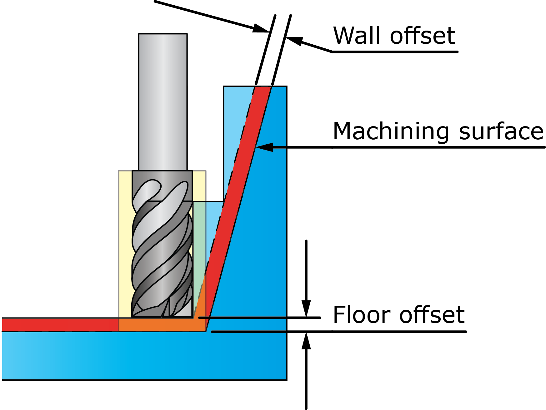
The iMachining 3D tool path is calculated by first taking into account the tool plus Wall offset and then by offsetting the tool along the tool axis by the distance equal to the Floor offset.
|
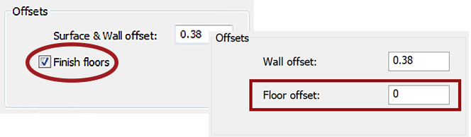
When opening 2013 and earlier CAM-Parts in SolidCAM 2021, if the Finish floors option was enabled in the Offsets section of an operation, then a Floor offset of 0 is automatically specified for that operation.
If the Finish floors check box was not enabled in an earlier version, then the default value is applied. |
Cutting angles
This section defines the Angle and Step over ranges for the operation. The values displayed in the locked text fields correspond to the Output Cutting Data shown on the Technology Wizard page.
When the Wizard is ![]() in the Operation dialog box,
the Cutting angles are shown with a
in the Operation dialog box,
the Cutting angles are shown with a ![]() icon because
they need to be synchronized with the selected set of Cutting conditions. If
you want to manually enter preferred values for the locked parameters,
the Wizard can be turned
icon because
they need to be synchronized with the selected set of Cutting conditions. If
you want to manually enter preferred values for the locked parameters,
the Wizard can be turned ![]() to open the
fields for editing.
to open the
fields for editing.
|
When using the iMachining technology, it is highly recommended to leave the Wizard On and utilize the optimal cutting angle and step over ranges that are provided. The Wizard automatically calculates these values and manages synchronization across step down, step over, spindle speed and feed rate. |
Finish
In iMachining 2D, the specified Technology type determines what tool path options will appear in this section of the Operation dialog box.
Floor
All technologies support the Floor option, which enables you to define the finishing of the pocket floor. When selected, a finishing cut is executed to remove the Floor offset. A Floor offset value greater than 0 must be specified in order to use this option.
The floor finishing tool path is performed according to the selected Style:
- Contour
– this style finishes the floor with a number of equidistant
contours parallel to the pocket walls. The Overlap % parameter defines the tool overlapping
between two successive passes, specified as a percentage of the tool
diameter. When the Floor option is enabled, this style
is the default selection with a 50% overlap.
- iMachining
– this style finishes the floor with iMachining tool
paths, consisting of morphing spirals and constant load one-way tool
paths.
For iRough and iRest, the specified Wall/island offset will remain on their respective contours after the floor finishing.
|
In the instance of a completely open pocket, where there are no walls or islands, an iRough operation alone can be defined to perform the rough and finish machining of the pocket floor. |
Wall
The iRough + iFinish and iFinish technologies support semi-finishing of the walls.
Semi-finish
This option adds a semi-finishing cut to the operation. The Offset parameter defines the machining allowance that will remain on the pocket walls/islands before executing the finish pass.
When the Semi-finish option is enabled, the default Offset value is automatically calculated and dynamically updated according to half the Wall/island offset to minimize your operation entries.
If you have a preferred value for semi-finishing, it can be manually entered after selecting the Offset override check box.
|
When using the override, associativity of the Offset value with the Wall/island offset will be broken. |
When executing the finish pass, any one or more of the following tool path options can be performed:
Finish quality
iMachining 2D enables you to define the finish quality of the wall and floor surfaces using Ra values.
Ra (Roughness average) is the most widely used one-dimensional roughness parameter that measures the microscopic peaks and valleys of a surface, describing its arithmetical mean deviation. Expressed in micrometers (microinches), the default Ra values are 0.8 µm (32 µin) for the Floor and 0.05 µm (2 µin) for the Wall. A larger number specifies a rougher surface with more deviation. A smaller number specifies a smoother surface with less deviation.
Only the iRough + iFinish and iFinish technologies enable you to define the Wall finish quality. All iMachining 2D technologies enable you to define the Floor finish quality only when the Floor option is selected. When not selected, the Floor (Ra) parameter is inactive.
The specified Ra values affect the finish feed rates automatically calculated for the tool, which are shown on the Data tab of the Tool page. Increasing the Floor (Ra) value produces a higher Finish feed floor value. Increasing the Wall (Ra) value produces a higher Finish feed XY value. Decreasing the Wall or Floor surface roughness produces correspondingly slower feed rates.
Morphing spiral factors
This section enables you to control the Efficiency and Entry rate of the morphing spiral tool path.
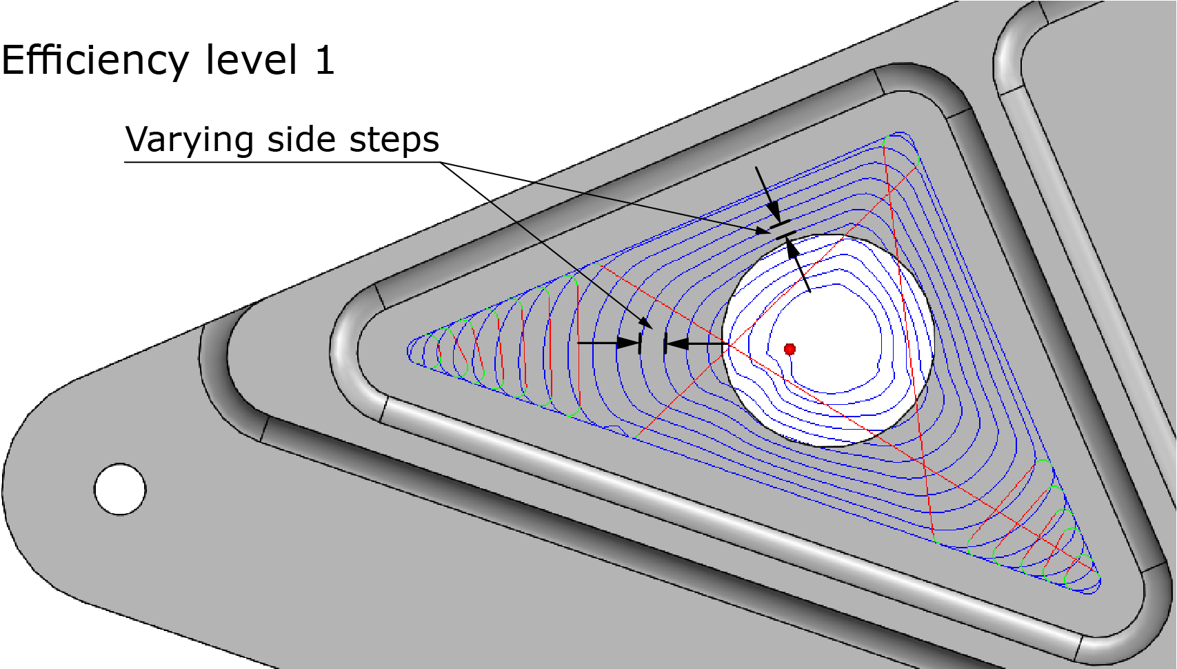
Spiral efficiency
The iMachining technology generates morphing spirals to clear a completely open or completely closed pocket area that does not have the shape of a circle. This means that it generates tool paths with different side steps in different directions.
As a result, the average side step is smaller than the maximum side step, which makes the average Material Removal Rate (MRR) less than the maximum MRR possible. This means that a morphing spiral is potentially less efficient than a regular round spiral.
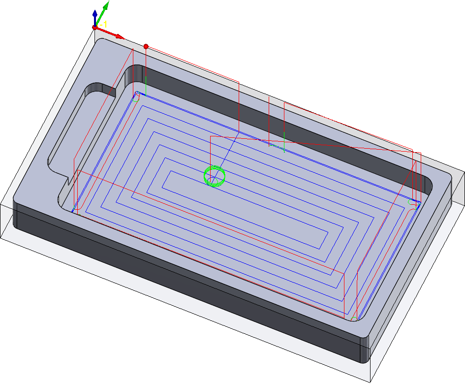
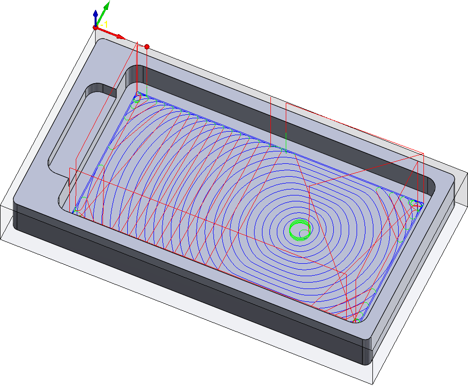
The Efficiency slider enables you to control the efficiency of the morphing spiral tool path. The examples below illustrate the effect of using this slider.
Increasing the efficiency reduces the Step over variation permitted in the spiral, which makes the side steps in all directions more equal and accordingly producing a rounder spiral, looking more like a circle. The remaining areas are cleared with trochoidal-like cuts.
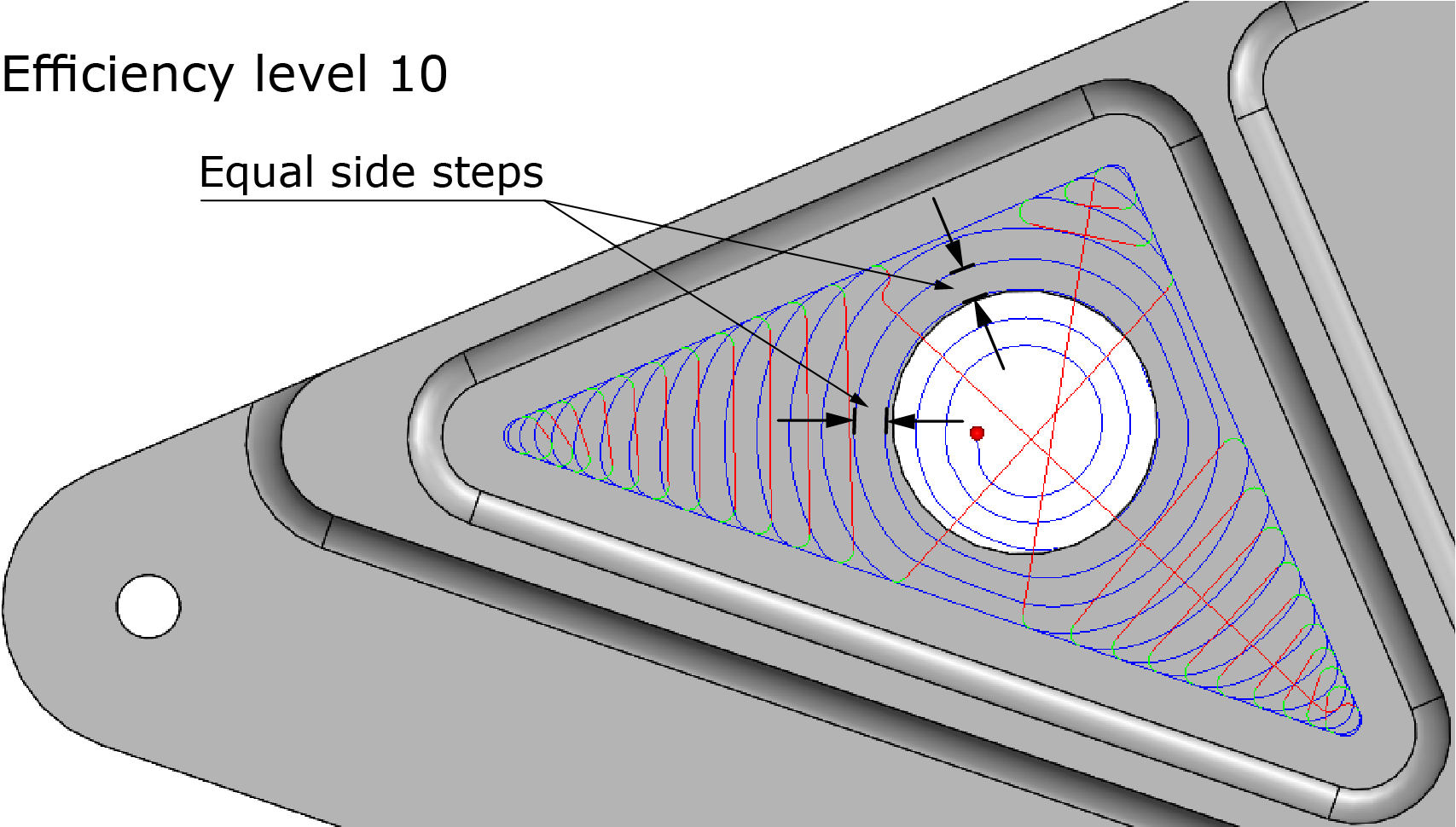
Decreasing the efficiency permits more use of the Step over range specified by the Technology Wizard. By managing to morph itself into narrower parts of the pocket, the spiral produced looks less like a circle and covers a greater part of the total area.
|
Level 6 is the default position of the slider and is recommended for all your general machining applications. |
There are three reasons why the iMachining technology permits control over the efficiency of the morphing spiral tool path:
Since the Technology Wizard adjusts the feed rate at every point along the tool path in order to maintain a constant cutting force on the tool, the actual loss in the average MRR is negligibly small or even zero. This greatly depends on the maximum feed rate the machine can achieve. With very slow machines, the Wizard cannot fully compensate for some of the very small side steps indicated by the morphing action, because the maximum feed rate of the machine is not high enough. In such cases, if your first priority is high average MRR, and long tool life is less of an issue, you can then limit the extent of the morphing action by selecting a higher level of spiral efficiency.
The second reason is to gain a higher global efficiency for the whole pocket or part; because of this, the iMachining technology is willing to sacrifice a little in the local efficiency of a specific spiral by using a default Efficiency level of 6.
The third reason is to extend tool life to the maximum possible; because of this, a low Efficiency level is used since it is proven that a continuous spiral cut causes less wear on the tool than repeated short trochoidal-like cuts.
|
Priorities and cost structure (relative cost per part of machine time, tooling and labor) are the determining factors for what level is best. Although it will increase the cycle time, a lower level is usually best when regularly using expensive tools. |
Entry rate
When the ![]() mode is enabled in the Operation dialog box, the Entry rate slider appears
on the Technology page.
mode is enabled in the Operation dialog box, the Entry rate slider appears
on the Technology page.
All morphing spirals approach the stock material from air, whether it is from the outside of an open pocket in the case of a converging spiral or from the inside of a closed pocket (using a pre-drill or helical entry) in the case of a diverging spiral.
The Entry rate slider enables you to control the rate at which the morphing spiral tool path first enters the material. The rate of entry is automatically set by the Technology Wizard in accordance with the Material Properties. The examples below illustrate the effect of using this slider.
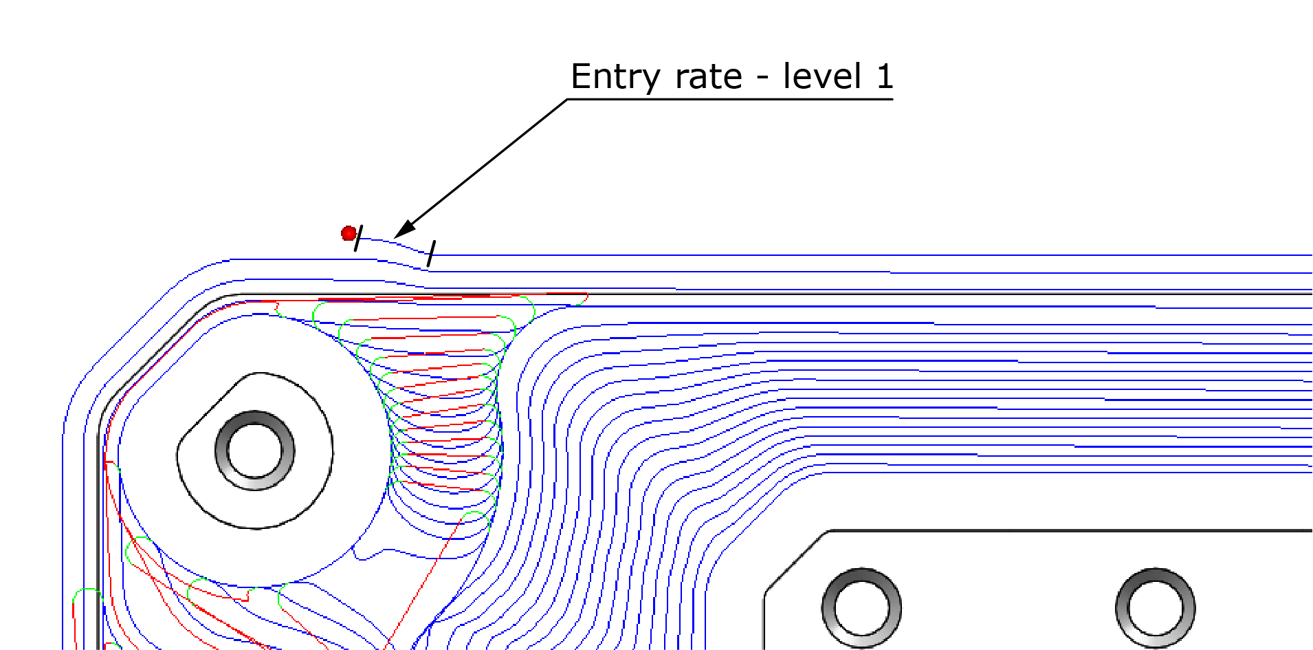
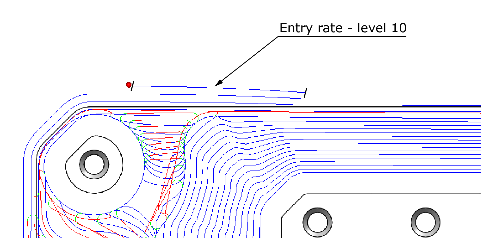
The value displayed to the right of the slider only indicates the relative rate of entry and has no fixed units.
|
For hard materials, it is better to enter the material more gradually than to directly lead in to the initial radial depth determined by the side step that is appropriate for the specific shape of a morphing spiral. |
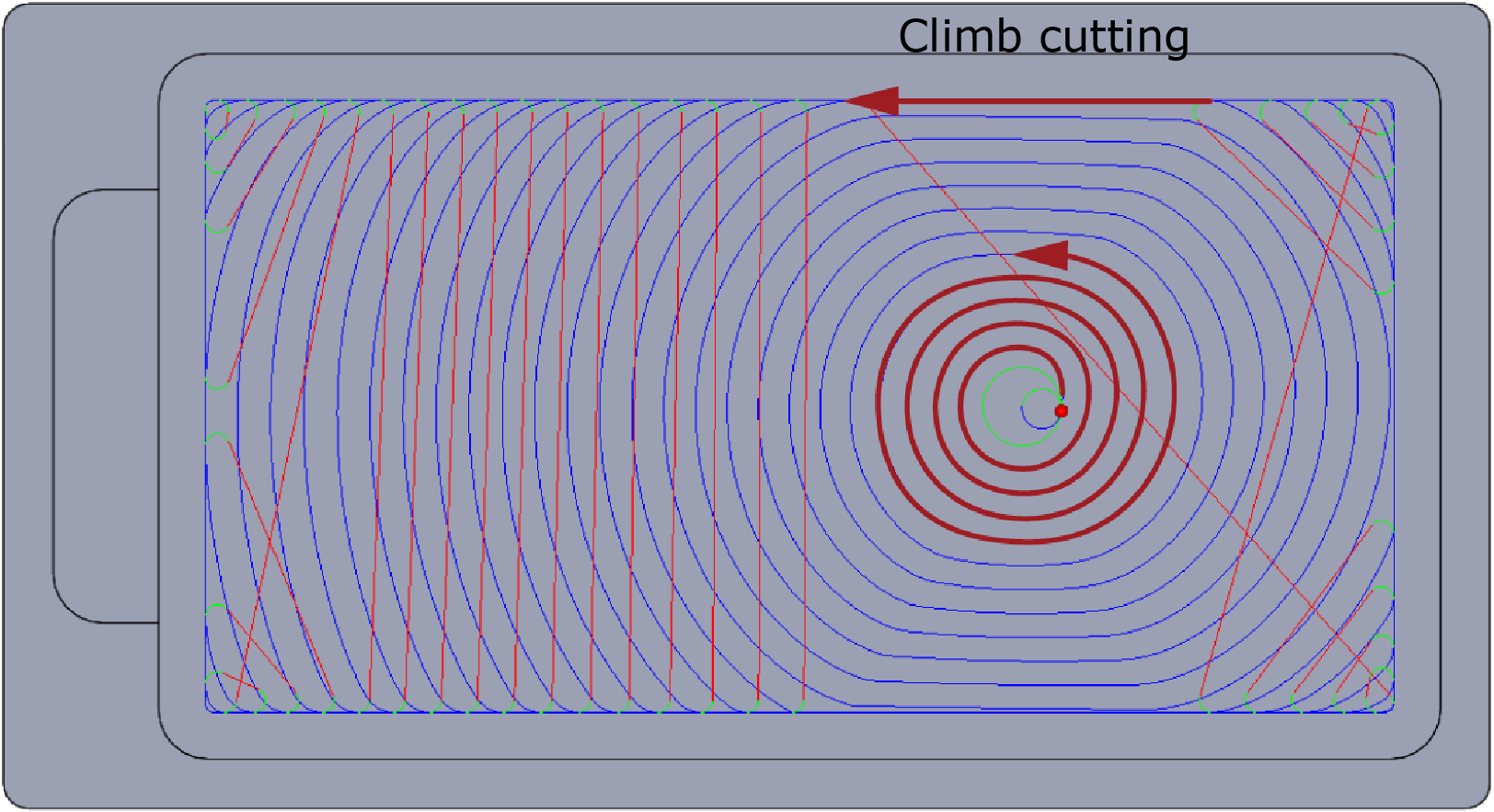
Cutting direction
Both iMachining 2D and iMachining 3D enable you to choose the Cutting direction of the tool path.
The tool path cutting direction is performed according to the selected Style:
Climb
By default, the iMachining technology performs Climb cutting with one-way (trochoidal-like) tool paths to machine narrow passages, separating channels and tight corners.
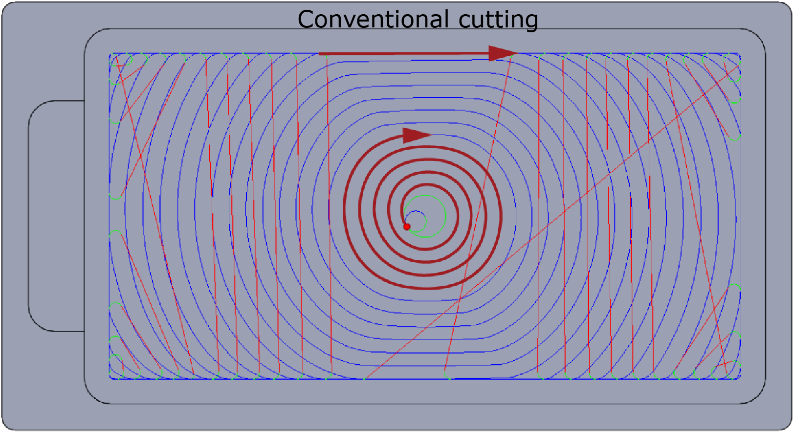
Conventional
The Conventional option enables you to perform a similar style tool path as the aforementioned but in the opposite direction.
|
Unlike other SolidCAM operations, the cutting direction calculations in iMachining are unaffected by the operation geometry chains. |
Climb/Conventional – Zigzag
Instead of one-way (trochoidal-like) tool paths, you can choose to perform Climb or Conventional cutting with a Zigzag tool path to connect the cuts. When machining narrow passages, separating channels and tight corners, the cutting direction changes from cut to cut containing both climb and conventional movements.

Tolerance
In iMachining 3D, the parameters specified for the tool and the operation are used to calculate the single steps of the tool on the mathematical model, which results in a PCode file that is given the *.pj file extension. It later serves as input to the generation of the GCode file.
The Tool path parameter defines the accuracy of the tool path generation by affecting the number of single steps in the tool path. By default, this value is automatically calculated based on the current tool diameter.
If necessary, an override check box is provided for specifying a different value.
|
A smaller value will result in less deviation from the mathematical model, but the calculation time will be proportionately longer. |