Partial Machining dialog box
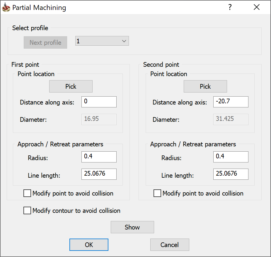
Select profile
This section enables you to choose the chain for which the partial machining will be used. Choose the number of the chain in the combo box. The Next profile button enables you to automatically switch to the next chain in the geometry.
First point/Second point
The First point and Second point sections enable you to define the profile segment that will be machined in the operation and the parameters of the tool approach/retreat movements.
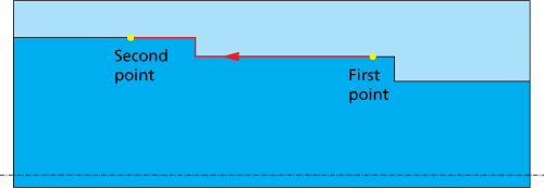
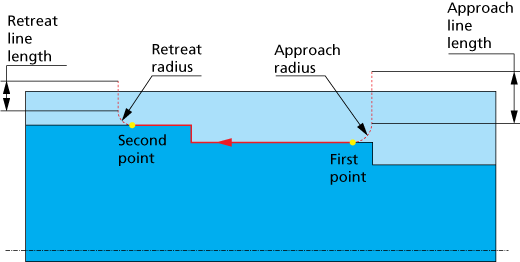
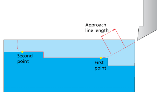
The generated partial cutting pass is performed between the first and the second point; the cutting pass direction is determined according to the Profile direction option.
SolidCAM automatically generates the approach and retreat passes at the first point and the second point according to the machining direction. In the illustration below, the approach movement is performed at the second point and the retreat movement at the first point.
The approach/retreat passes consist of an arc tangential to the partial machining geometry at the first/second point and a line connected to the arc. The line direction is automatically chosen according to the Tool type, Tool tip angle and Safety angle parameters.
Point location
This section enables you to define the location of the first point and the second point.
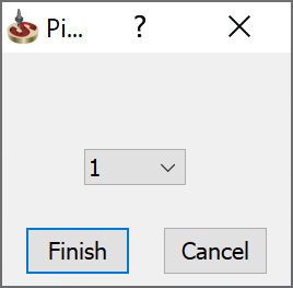
The Pick button enables you to select the approach and retreat points directly on the model geometry. The Pick First point/Pick Second point dialog box is displayed.
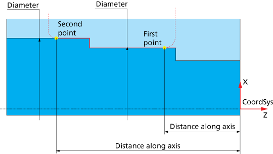
When the point has been picked, SolidCAM calculates the Distance along axis and Diameter values for the picked point and displays in the Partial machining dialog box.

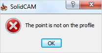
When the first/second points are picked outside the geometry, the error message is displayed.
This option displays the distance from the CoordSys to the first/second point along the Z-axis. If the Pick option was used, the value is calculated automatically. This option can also be used as an alternative to the Pick option to define the first/second point locations. Even if the Pick option was already used, you can edit the value received from the model and change the first/second point locations.
This field displays the value of the part diameter at the specified location, which is calculated automatically according to the geometry and the Distance along axis value. When there are several Diameter values for a single Distance along axis value, SolidCAM chooses the maximal Diameter value determined.
Approach/Retreat Parameters
These parameters enable you to define the approach/retreat passes:
This field defines the radius of the approach/retreat arc, which is tangential to the profile at the first/second point.
This field defines the length of the straight line tangential to the arc. The direction of the approach/retreat lines, connected to the approach and retreat arcs, is chosen according to the Tool type.
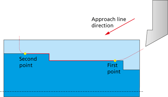
The scheme below illustrates the approach line direction for an External Rough tool.
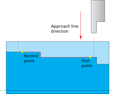
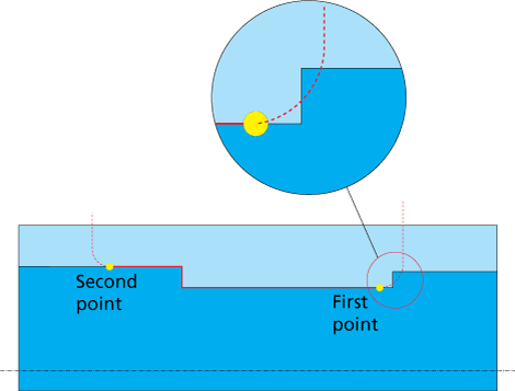
The scheme below illustrates the approach line direction for an External Groove tool.
When the approach/retreat lines are located inside the Material boundary of the pre-machined stock, SolidCAM automatically extends them till the Material boundary.
Modify point to avoid collision
This check box enables you to perform automatic modification of the defined first/second point according to the geometry. The point modification enables you to avoid possible collisions during approach/retreat movements.
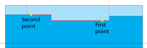
The image below illustrates the non-modified second point.
The collision possible during the approach movement can be avoided by the automatic point modification.
Modify contour to avoid collision
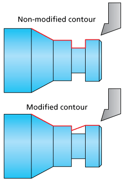
This check box enables you to perform the modification of the partial machining geometry.
When this check box is selected, SolidCAM performs geometry modification according to the tool shape. The modification enables you to avoid possible collisions between the tool and the geometry during the machining. The machining geometry is changed in areas where possible collisions are detected. The geometry is changed taking into account the tool shape.
This check box is relevant only for semi-finish and finish machining with Finish only Work type. In Rough Work type, the geometry modification is automatically performed, regardless of whether this check box is selected.
The Show button enables you to display the machining geometry and the updated partial geometry between the first and second points with the tangential arcs and connected lines.
Related Topics