Technology page
Modify
This section enables you to change the tool side relative to the chosen geometry.
Tool side
The tool can cut to the left of the profile, to the right of the profile, or directly on the engraving geometry.
- Right: the tool cuts to the right of the profile geometry up to a distance defined with the Wall offset value.
- Left: the tool cuts to the left of the profile geometry up to a distance defined with the Wall offset value.
- Center: the center of the tool moves directly on the profile geometry.
Geometry
Clicking this button opens the Modify Geometry dialog box that enables
you to perform Chain modifications such as include/exclude chains from
the defined geometry. If the geometry has been modified, the ![]() icon is displayed next to the Geometry button.
icon is displayed next to the Geometry button.
Side offset
This option defines the offset that remains on the wall after semi-finish for finish operation.
|
The Side offset parameter is available only for Right or Left tool side, when you choose the Semi-finish option. |
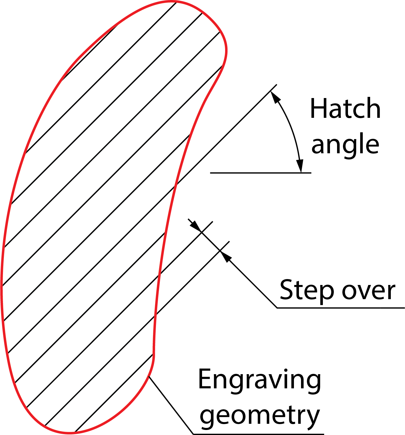
Fill area
The area within the closed engraving geometry can be machined using the following strategies:
Hatch
SolidCAM fills the engraving geometry with a linear raster tool path, according to the specified Step over and Hatch angle.
Related Topics
Contour
The tool moves on offsets parallel to the pocket contour with the specified Step over.
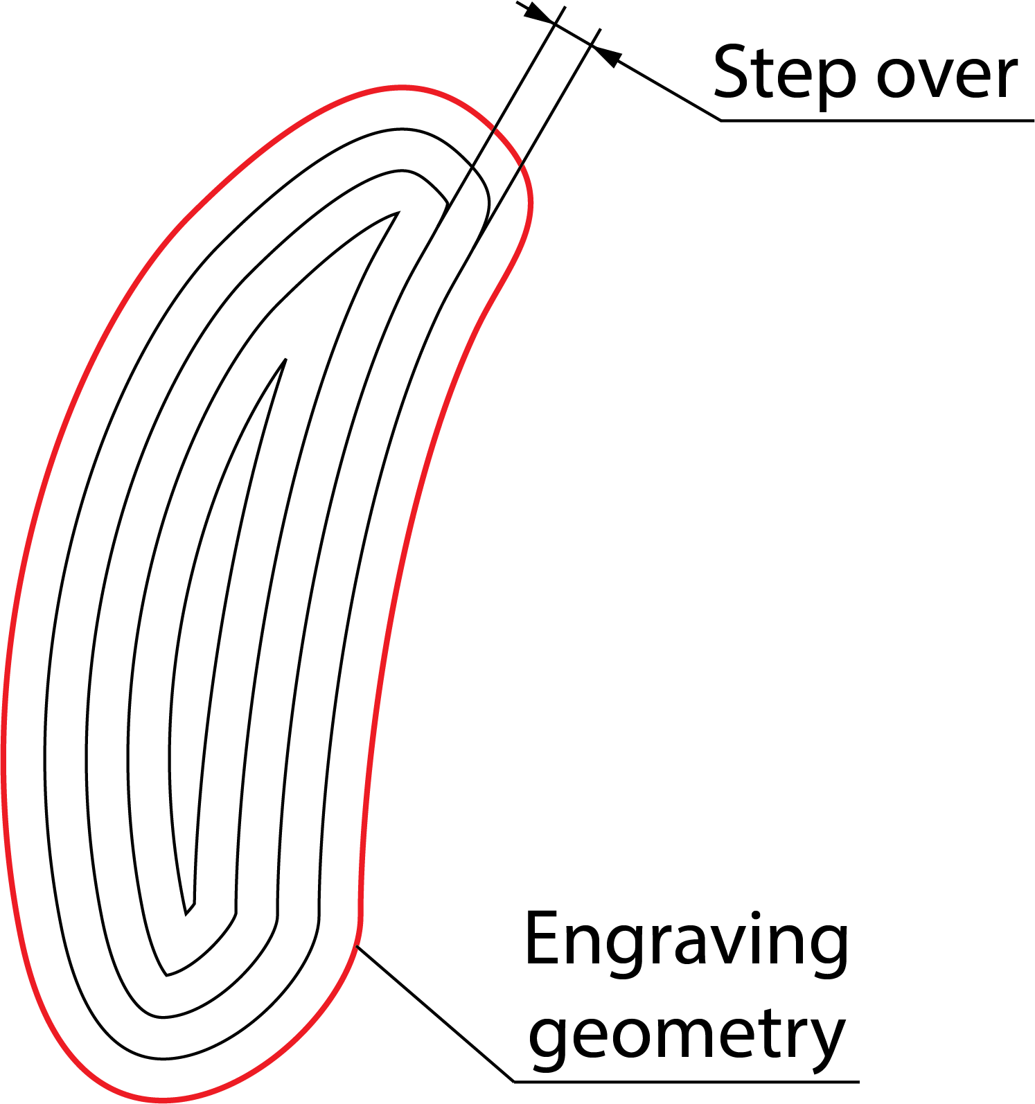
The contours are machined in the clockwise (CW) or counterclockwise (CCW) direction.
Related Topics
Middle line only
The tool moves along the middle lines of the closed profiles.
When this option is chosen, you cannot select the tool side: it is always set to Center by default.
Min. contact angle
The tool moves along the middle line unless the contact angle is smaller than the Min. contact angle. This is a minimum angle between two normals at the contact points between the tool and walls. The default value of the Min. contact angle is 100.
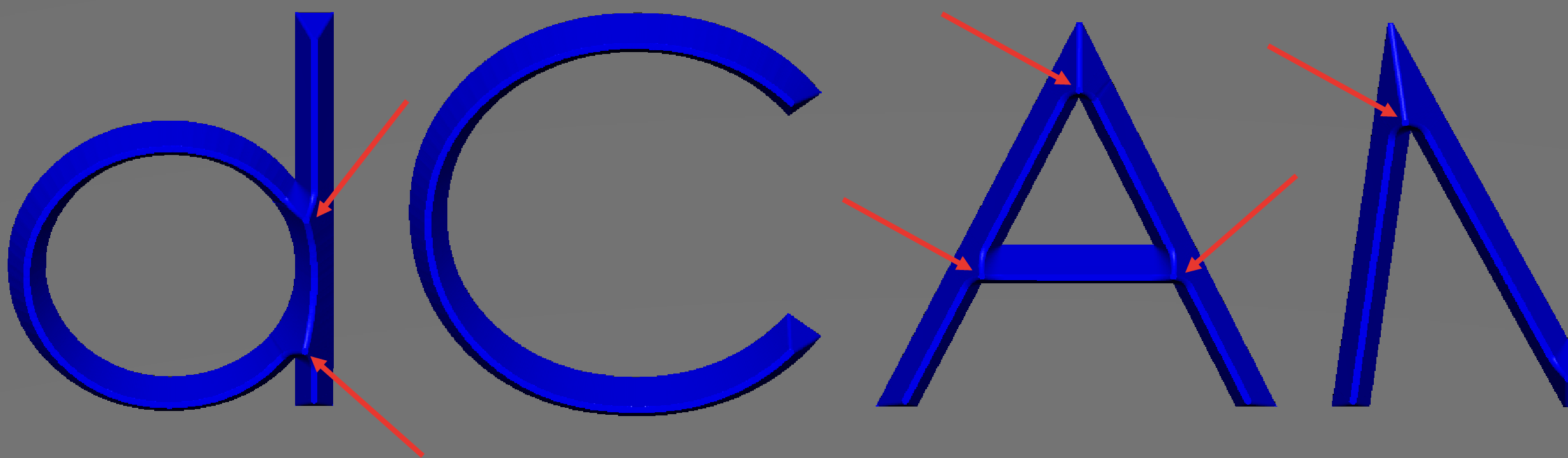
V-carving
Selecting this check box, creates a 3D tool path from 2D Font. Set the Min. contact angle to 60 or less for improved results. When V-Carving is enabled, the Engraving depth on the Levels page is set to 0 and locked from editing because the depth varies. The varying depth, which is a result of the operation maintaining the font appearance on the engraving surface, is determined automatically by the tool tip geometry and width of the font.
In the image below, you can see that the engraving tool machines deeper in the wider areas of the font.
|
The Offsets options are disabled when you use the Middle line only option. |
Depth cutting type
This section enables you to choose the contour cutting type.
Offsets
Wall offset
This option defines the offset that remains on the wall to be machined during the finishing cut.
Floor offset
This option defines offset in the Z-axis direction, which is left after semi-finish for finish operation.
|
The Floor offset parameter is available only for 2D Engraving operations, when you choose the Semi-finish option. |
Semi-finish
This option enables you to perform additional cuts with a defined Step down.
The Step down field enables you to set the distance between passes in the Z-axis direction.
Cutting type
If you select the Horizontal passes option, the roughing passes are performed at each down step, from the upper level to the virtual surface located at an offset from the actual surface.
If you select the Parallel to surface option, the roughing passes are performed at each step down, only from an actual surface to a virtual surface defined with the Engraving depth value.
|
The Cutting type option is available only for 3D Engraving operations. |
Floor finish
This option enables you to define the final cut of engraving.
2D Engraving options
Compensation
When the Compensation check box is selected, SolidCAM generates the trajectory of the tool center as an offset by the tool radius from the geometry.
At the next stage, SolidCAM creates the tool path as the offset by the tool radius from the tool center trajectory. The offset is created in the geometry direction.
Complete Z-level
This option enables you to define the order of the machining Z-levels.
Link between...
Rapid through clearance level
After the machining of the specific Z-level (Links between passes) or the specific chain from the multi-chain geometry (Links between chains), the tool retracts up to the Operation Clearance level. At this level the tool horizontally moves to the start position of the next cutting pass or geometry chain and then descends to the next Z-level.
Feed through safety from surface
After the machining of the specific Z-level (Links between passes) or the specific chain from the multi-chain geometry (Links between chains), the tool retracts up to the height equal to the Safety distance from the machined level, then horizontally moves to the start position of the next cutting pass or geometry chain at this level and descends to the next Z-level.
Rapid through safety from surface
After the machining of the specific Z-level (Links between passes) or the specific chain from the multi-chain geometry (Links between chains), the tool moves directly to the start position of the next cutting pass or geometry chain at this level and descends to the next Z-level.
3D Engraving options
Tool path tolerance
SolidCAM generates the tool path in two steps:
- SolidCAM generates a mathematical representation of the surfaces and solids of the 3D Model geometry within the given facet tolerance. The information about this triangulation process is stored in an internal *.fct file that is similar to an *.stl file.
- SolidCAM calculates the tool path using the parameters specified for the tool and the milling strategy to calculate the single steps of the tool on the mathematical model created in the first step. The result of this calculation, the *.pj PCode file, later serves as input to the generation of the actual GCode file. During this calculation, SolidCAM uses the Tool path tolerance that affects the number of single steps in the tool path (accuracy of the tool path).
The accuracy of the tool path depends on the Tool diameter and the specified tolerance value.