Data
This tab enables you to define the feed, spin and tool offset parameters for the tool chosen in the operation. When the tool is chosen for the operation, SolidCAM fills this dialog box with the default data of the selected tool. The parameters relevant to the particular operation are selected from the Feed & Spin tab in the ToolKit Dialog box. This page enables you to edit the tool parameters for the specific operation only.
The Feed values can be displayed in the following two types of units:
- F is the default type displaying units of distance per time.
- FZ displays the equivalent values in units of distance per tooth, which are calculated according to the formula FZ = F/(Number of flutes × S).
The Spin values are displayed in the following two types of units:
- S is the default type displaying revolutions per minute.
V displays the equivalent values for material cutting speed (velocity between the edge of the cutting tool and the surface of the workpiece), which are calculated according to the formula V = (S × π × Diameter)/1000 for Metric units and V = (S × π × Diameter)/12 for Metric units.
Feed
This section defines the feed rate of the tool
- Feed XY - Feed rate in the XY plane.
- Feed Finish XY - Feed rate used for finish milling. The Feed finish XY check box enables you to optionally define different values for Feed XY. When this check box is selected, the corresponding edit box is available so that you can edit its value. When this check box is not selected, the specified Feed XY value is used for both rough and finish machining.
|
For Drill and Tap tools, the Feed XY and Feed Finish XY parameters are not relevant. |
- Feed Z - Feed rate in the Z direction.
Feed Link, % - feed rate used for tool path linking movements.
|
This option is available only for Face Milling and Engraving operations. |
Feed Lead In/Out, % - feed rates used for approach and retreat tool movements.
Feed Between Holes - In a Drilling operation, Feed Between Holes is by default set to the Max feed chosen in the VMID of the Axis.
Feed reposition, % - feed rates used for the tool repositioning motion within spiral cuts in the Toolbox cycles spiral cutting strategies. This parameter enables you to define the feed as the percentage of the cutting feed (Feed XY).
Feed Z - for penetration only - When this check box is selected, the defined Feed Z is used only for vertical movements. When this check box is not selected, the defined Feed Z is used for all movements when the Z-coordinate changes.
|
This option is available only for Profile, Contour 3D, Pocket, Pocket Recognition and Engraving operations. |
Spin
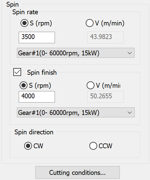
This section defines the spinning speed of the tool by the following values:
The Spin finish check box enables you to optionally define different values for Spin rate and Spin finish. When this check box is selected, the corresponding edit box is available so that you can edit its value. When this check box is not selected, the specified Spin rate value is used for both rough and finish machining.
|
1. Spin S (RPM): The spin value is automatically corrected to maximum from the gear when: a. The Tool spin (from tool table) is bigger than Max Gear. b. Inside a job, you insert a Spin value S (RPM) that is bigger than Max Gear.
2. Spin (V): Automatically corrects V value to value that corresponds to RPM Max value from Gear when: a. The Tool spin (V) (from tool table) gives bigger RPM than Max Gear. b. Inside a job, you insert the value of Spin (V) that gives you a bigger RPM than Max Gear. |
Gears
If the drive system of your CNC-Machine has two or more gears with different spin limitations, they can be individually defined in the VMID's Drive Unit settings. When more than one is defined, you can select your preferred gear for use in the operation from the Gear list. By default, the gear is automatically selected according to each of the Spin values. Only gears having the current Spin value within their range are shown in the list.
The first parameter enclosed in parentheses indicates the defined spin range; the second parameter indicates the defined power.
The Spin direction section enables you to choose between the clockwise (CW) or counterclockwise (CCW) direction.
Offsets
Length offset number
This parameter defines the number of the Length Offset Register of the current tool in the Offset table of the CNC-Machine.
Cutting conditions
This button enables you to update the cutting conditions defined for use of the current tool on the chosen CNC-Machine according to the parameters set in the Cutting Condition Data.
Related Topics