Limits
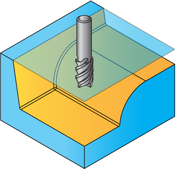
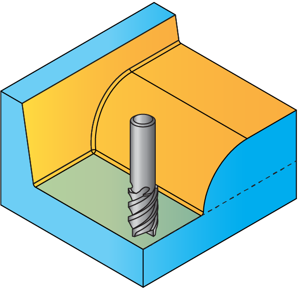
The limits are the highest and lowest Z-positions for the tool - the range in which it can move.
 |
|
This limit is used to limit the passes to level ranges or to prevent the tool from falling indefinitely if it moved off the edges of the model surface. When the tool moves off the surface, it continues at the Z-Bottom limit and falls no further. |
 |
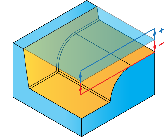
If the Delta value is positive, a blue arrow is displayed near its field indicating a positive offset value (in the positive direction of the Z-axis). If the Delta value is negative, a red arrow is displayed near its field indicating a negative offset value (in the negative direction of the Z-axis). |
 |
CoAngle- This parameter defines the contact angle alignment to be used when making cross machining passes.
|
This option is available only for the Linear finishing strategy. |
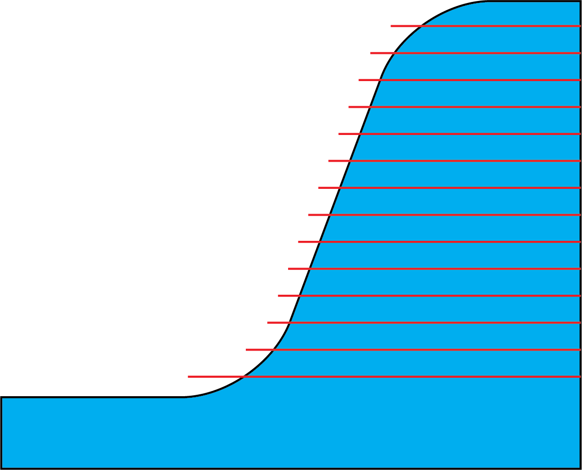
Angle- SolidCAM enables you to limit the surface angles within a range most appropriate to the strategy. The Constant Z strategy, for example, is most effective on steeper surfaces, because the spaces between the passes are calculated according to the Step down value, and on surfaces where there is little Z-level change, the spaces between the passes are greater, therefore you may get unsatisfactory results. You can limit the work area to surface angles between, for example, 30 and 90 degrees.
The angle is measured between the two normals at the contact points between the tool and model faces. The angle of 0 means coincidence of surface normal and tool axis (horizontal surface).
|
This option is available for the Constant Z, Linear, Radial, Spiral, Morphed, Boundary, 3D Constant Step over, and Pencil Milling strategies. |
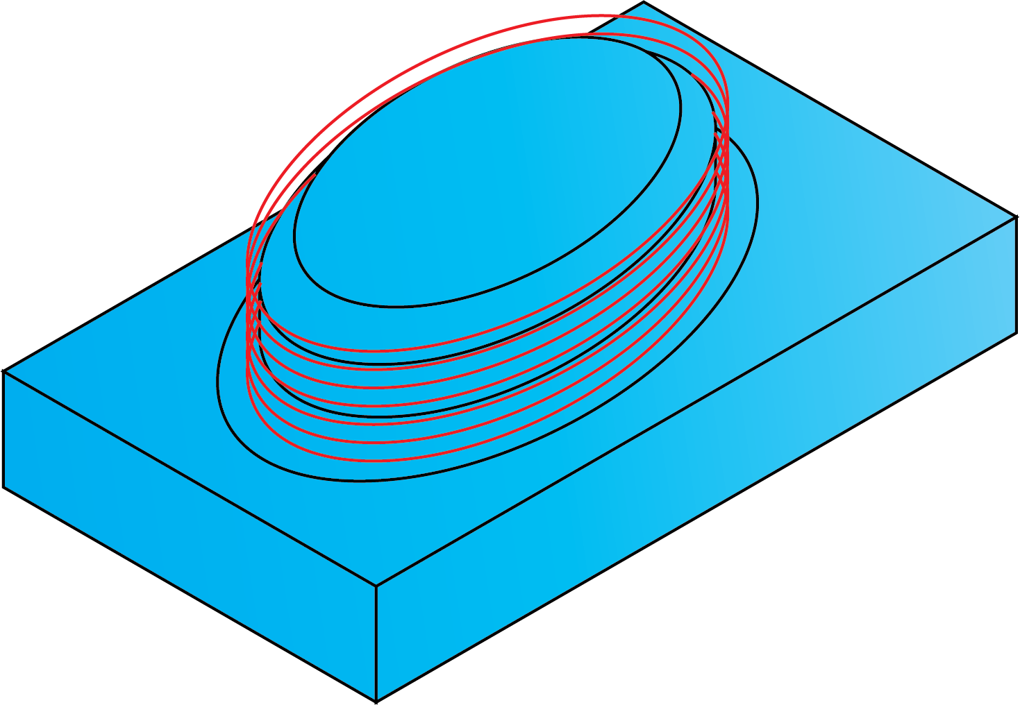
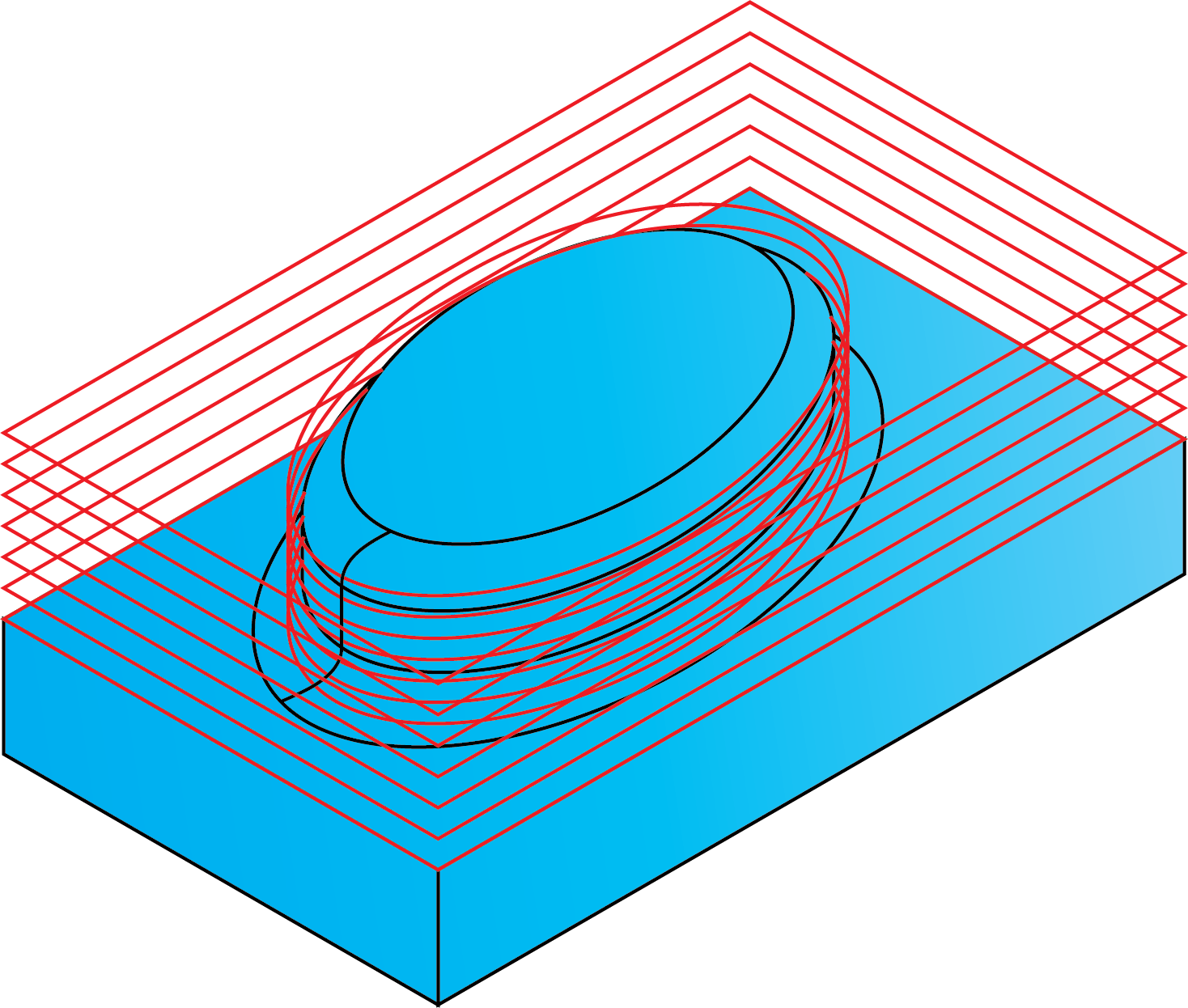
When this check box is selected, the tool path is only created where the tool is in contact with model faces. The examples below show the result of Constant Z strategy with and without the Contact Areas Only option.
When this check box is selected, the machining is limited to the actual surfaces of your geometry.
When this check box is not selected, the outer edge of the base surface is machined as well as the central boss.
Related Topics