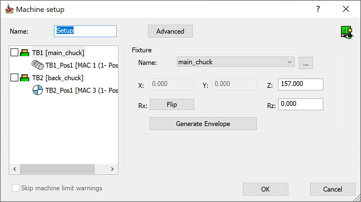
Machine setup dialog box
The Machine Setup enables you to define relations between Submachines, Machine Coordinate System with shifting, and Fixture.
To define a new Setup:
- Right-click the Operations header in the CAM Manager tree and from the Machine Setup submenu, choose either Add at start of operations tree or Add at end of operations tree to specify the location for adding the setup. The Machine setup dialog box is displayed.
|
You can also right-click any existing operation and from the Machine Setup submenu, choose to add the setup Before or After the selected operation. |
- In the Name field, type a new setup name or use the default one. This name will be displayed in the CAM tree.
![]()
- The Table Tree View by default displays the Table name and Position number of the respective table (fixture) or None. Right-click on Table name and Position number to edit Stock in.
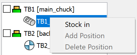
The Stock in option enables you to specify the part location on the machine table. Only one table at a time can hold the part.
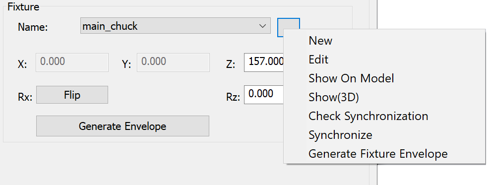
- Clicking Table displays
the Fixture field. The Fixture
field enables you to choose or define the fixture to be used with
the specified table. To define the fixture, click the drop-down list
and choose ... or, click
 and select
New. The Model dialog box is displayed.
and select
New. The Model dialog box is displayed.
|
 |
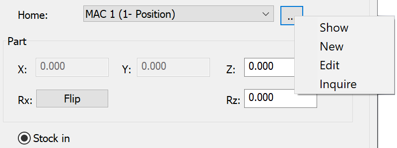
Clicking Table Position displays the Home field. The Home field displays the list of defined coordinate systems. Click
displays to Show, New, Edit and
Inquire a CoordSys.
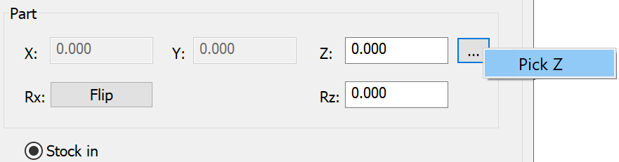
- You can define the linear and rotary values for Z axis for fixture and part.
Flip enables you to flip the fixture or part to the opposite direction.
- Generate Envelope enables you to create an envelope for the fixture model.
- The Z coordinate defines
the Part's origin position relative to the Machine Coordinate System
position. The Z value for the part can be defined as well as chosen
by clicking
. When you click you can Pick Z point directly
from the part. Selecting Pick Z opens the Pick Point dialog box.
- The Stock in option can be enabled by right-clicking Table name and Position number or, selecting Table name and Position number.
- Selecting Advanced enables you to define the X and Y axis rotary values for fixture and part.
Click the check box before the Table name in the tree view to display the fixture directly on the model.
When you complete the Setup definition by clicking OK, SolidCAM adds the Setup item to the CAM Manager tree according to the chosen location. To manage an existing Setup, right-click the subheader and choose a command from the menu.
Machine Preview
Machine Preview ![]() enables you to display the Machine
Preview dialog box to quickly visualize the schematic position of
the machine devices without entering the Machine
Simulation mode.
enables you to display the Machine
Preview dialog box to quickly visualize the schematic position of
the machine devices without entering the Machine
Simulation mode.
Skip machine limit warnings
When Skip machine limit warnings is selected, SolidCAM will not display any error messages when checking the machine limits in the GCode output or during the Machine simulation. This option can be activated by changing the settings in the VMID file of the CNC-Machine.