Tool item properties specific to iMachining operations
If you are defining a Tool Item for use in iMachining operations, it is not necessary to specify the Feed & Spin data. The iMachining Technology Wizard uses the Cutter geometry to automatically calculate optimal sets of Cutting conditions specific to each operation.
The Topology parameters significant in iMachining calculations include:
- Diameter (D) - defines the Cutter diameter, which affects the automatically calculated values of several parameters in iMachining operations.
- Outside holder (OHL) - defines the Cutter length outside the Holder. The Technology Wizard modifies the chip thickness taking into account the Outside holder length (OHL). As the OHL increases, the chip thickness is reduced.
- Cutting (CL) - defines the Cutter length that performs the cutting. The Technology Wizard in Automatic mode uses the Cutting length (CL) to calculate if multiple steps are needed to achieve the total depth [of the pocket].
- Number of flutes - defines the number of Cutter teeth. The Technology Wizard relies on the correct number of flutes to ensure the appropriate chip thickness is calculated per tooth. Changing the number of flutes will change the feed rate of the Cutting conditions.
In addition to the above parameters, there are additional Cutter properties specific to and used in iMachining operations.
In previous SolidCAM versions with Classic Tool Table, the iMachining specific properties could be found on the iData tab as shown below.
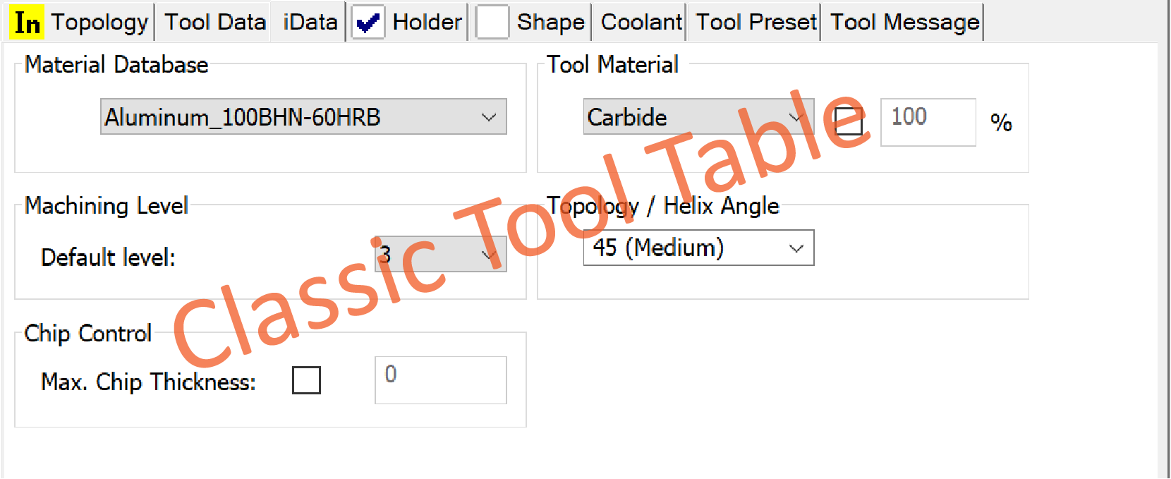
Cutting condition iData
In SolidCAM ToolKit, the iMachining specific properties have been reorganized as follows:
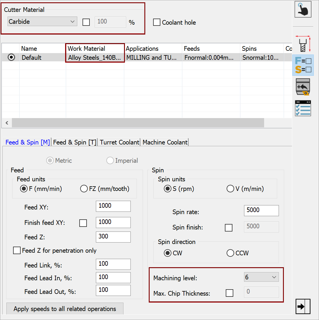
The Cutter Material option appears in the Cutting Condition Data. The pre-defined list enables you to select a given type of material from which the Cutter is made. The Cutter Material selection affects the Max. Cutting Speed adjustments generated by the Technology Wizard along with the associated Feed Rate Max and Max. Spin parameters. By default, the following options are available for selection:
- Carbide at 100% (default selection)
- Cobalt at 60%
- HSS at 40%
- Premium Carbide at 150%
If necessary, an override check box is provided for manually setting a percentage adjustment.
The Material Database selection appears in the Work Material column of the Cutting Condition table. When clicking the cell, the appearing list enables you to define a different work material that is associated to the Cutter.
|
A different work material is typically defined when using specific tools to machine different materials in one CAM Project (e.g., the CAM-Part versus a fixture). |
The Machining level and Max. Chip Thickness options appear on the Feed & Spin [M] tab of the Cutting Condition Data.
- Machining level enables you to assign a level different than the CAM-Part default that is specific to each Tool Item.
- Max. Chip Thickness is automatically calculated by the Technology Wizard, but you can instead specify a preferred value that is associated to the Cutter (e.g., that which is recommended by the tool manufacturer for the given type of Cutter Material).
|
Because this value is automatically calculated according to several factors, it is recommended not to specify a Max. Chip Thickness for any given tool. |
Topology iData
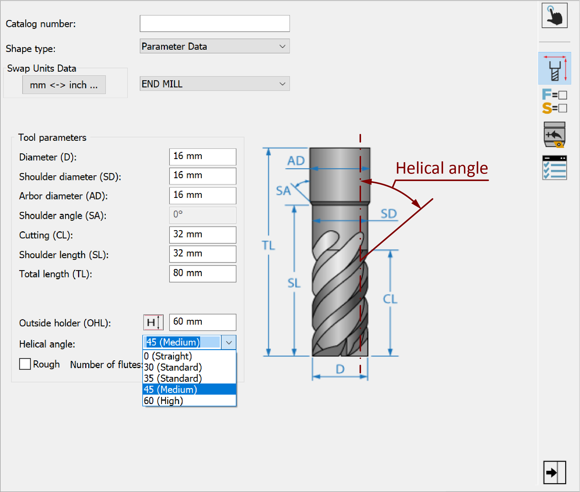
The Helical angle parameter appears in the Topology Data and is especially important for calculating depths based on Axial Contact Points (ACPs) of the Cutter. The drop-down list contains five typical flute helix angles available for selection:
- 0 (Straight)
- 30 (Standard)
- 35 (Standard)
- 45 (Medium) (default selection)
- 60 (High)
If necessary, a value can be entered manually.
Changing the Helix Angle parameter only changes the ACP indication on the Technology Wizard page of the iMachining Operation dialog box.
|
Warning: When cutting, keep in mind that the helix angle has a strong effect on the Downward Force on the tool, which should be monitored. If ignored, it can result in the tool being pulled out of its holder. |
It is critical that the iMachining specific properties are entered accurately so the Technology Wizard can calculate the correct and optimal Cutting conditions.
Once your Cutter component is added and its properties defined, you can finish assembling the Tool Item with additional components.
Related Topics