SolidCAMComponentsLib and Tool Holding System
SolidCAMComponentsLib is a predefined Tool Components Library that is included with the installation of SolidCAM. SolidCAMComponentsLib.tlv is installed in C:\Users\Public\Documents\SolidCAM\SolidCAM2021\Tables\Metric as well as in ...\Tables\Inch.
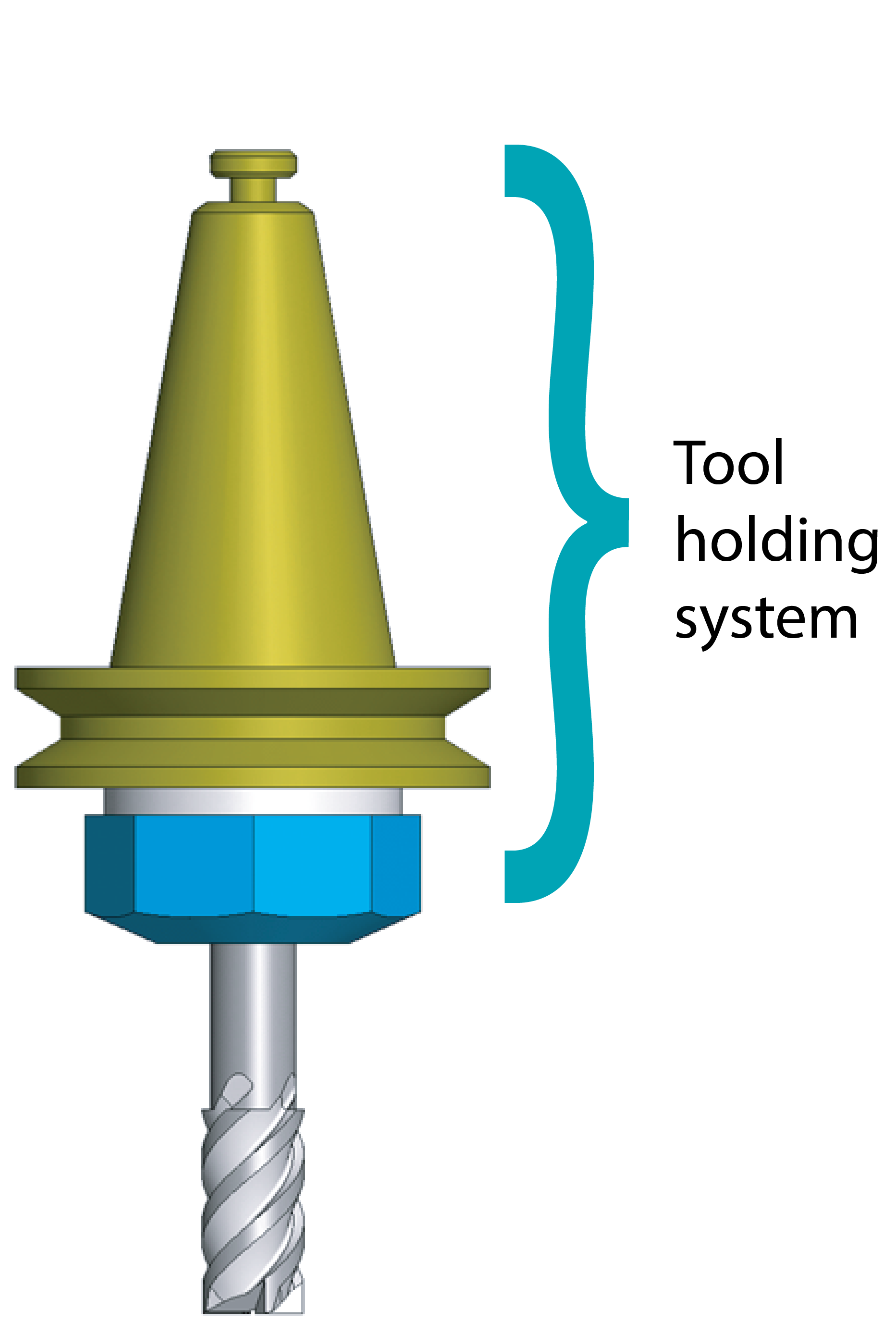
SolidCAMComponentsLib and the Tool Holding System SolidCAM enables you to define, edit and use a variety of Adaptors and Holders to help you check and prevent all possible collisions between your Tool Holding System and the workpiece. The SolidCAM Tool Holding System also provides a more realistic visualization of the machining simulation in the SolidCAM Simulator and SolidVerify Simulation modes. |
 |
SolidCAMComponentsLib is automatically loaded in the Selection Pane when Adaptors and Holders are added to the tool assembly. If you want to specify a different default Library, you can do so in the ToolKit Settings.

The included components assist in the Tool Holding System definition for your Tool Item. As described below, two types of Holders can be used.

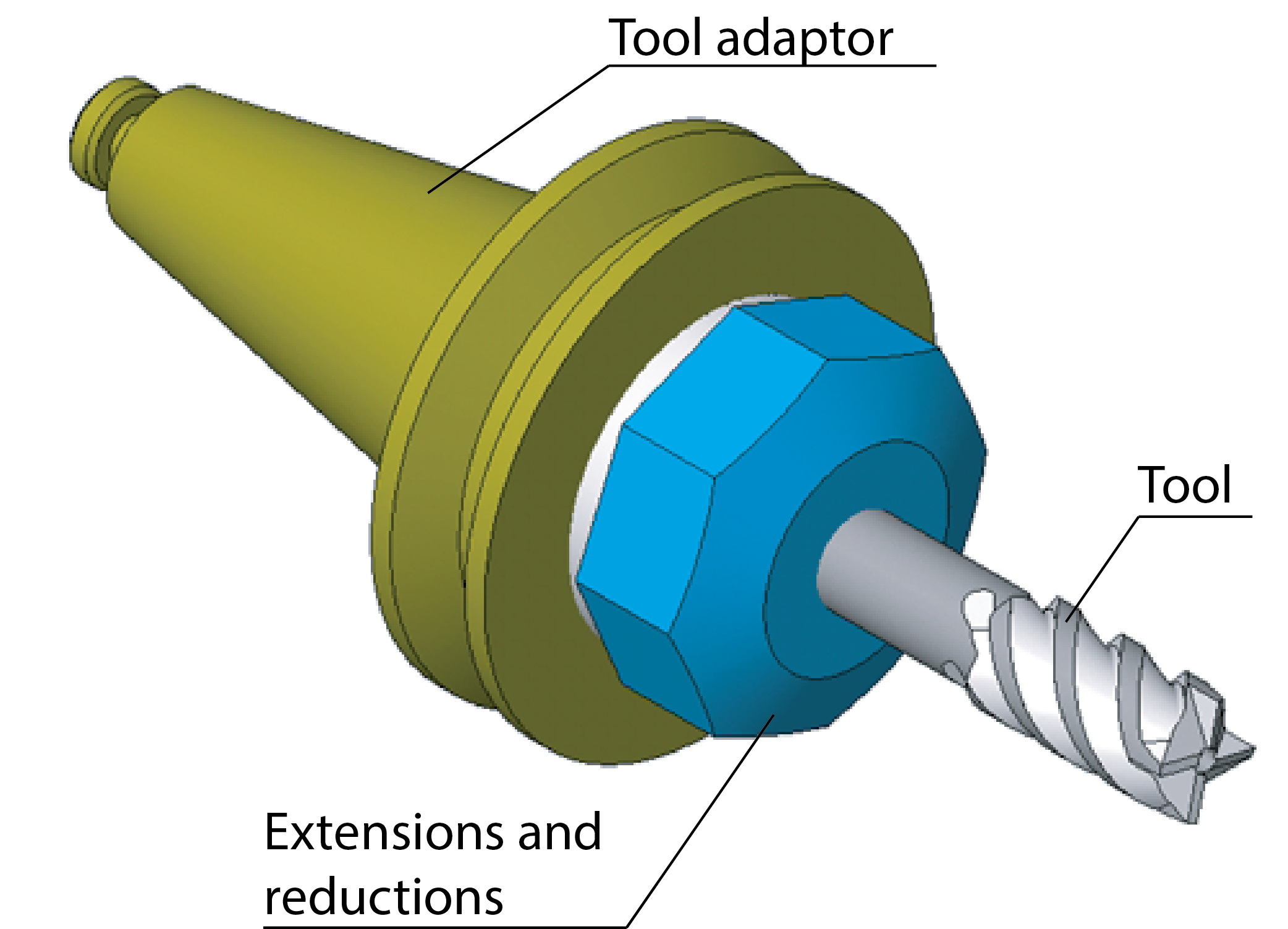
Standard/Shape Holder
A Holder of this type is comprised of two components. The first component is the adaptor and the second component can consist of different types of extensions and reductions such as collet chucks, arbors, shanks and other components you may have. There are a series of Standard Holders included in SolidCAMComponentsLib.
STL Holder
A Holder of this type is defined in the STL format. The STL file contains data on the shape and the visual properties of the actual Holder component. Like the provided Standard Holders, SolidCAMComponentsLib also includes a series of STL Holders.
Editing linked components
Components added from SolidCAMComponentsLib are linked to the .tlv library and shown with a link icon in the Tool Item Manager.

If you want to edit a linked component for use in your Tool Library, editing can be enabled with the Break Link command in the right-click menu of the Tool Item Manager.

When edits are made to the Components, SolidCAM offers the option to update their instance in any Storage of the Machine library. This is done with right click at the component node, and selecting Update Component from the options menu.
Defining/Editing Geometry
Whether new or existing, the Adaptor/Holder geometry can be defined and edited using the available Shape type options in the Topology Data of the component.

Sketch (2D)
The Sketch (2D) option displays an interactive picture of the Adaptor/Holder component, which is divided into segment shapes such as cylinders, cones and toruses.

Shapes can be added using the Toolbar or the interactive picture right-click commands. The actual dimensions can be edited by selecting the segments on the interactive picture and by using the corresponding Parameters pages.
3D Model (STL)
The 3D Model (STL) option enables you to define the Adaptor/Holder component by one or more STL/STEP files.

Using
the ![]() button in the STL Files
table, you can replace the current file with one of your choosing or you
can define an additional one in the next available row.
button in the STL Files
table, you can replace the current file with one of your choosing or you
can define an additional one in the next available row.
Related Topics